BIM documentation
Difference Between LOD 300 and 350: What Changes in a BIM Model?
The difference between LOD 300 and 350 is the information modeled at connections and coordination boundaries. At LOD 300, an element has measurable design geometry; LOD 350 also makes its relationships with adjacent or dependent elements measurable. The change helps teams examine installation interfaces, but it does not guarantee that a building model is clash-free or fabrication-ready.
This comparison explains BIM Level of Development, the geometry expected at each stage, and why supports, openings, and connections matter for coordination. It uses foundations and slabs-on-grade as technical examples, then compares practical model uses, LOD 400, and existing-condition records. A quick table appears first, followed by guidance for choosing requirements element by element.

LOD 300 vs LOD 350: What Is the Main Difference?
LOD 300 describes a model element with measurable designed dimensions and placement, while LOD 350 adds the modeled connections or interfaces needed for construction-level coordination. The higher designation concerns what users can evaluate about adjacent elements, not a universal improvement in survey accuracy. Both levels depend on the element-specific requirements adopted for the project.
| Comparison | LOD 300 | LOD 350 |
|---|---|---|
| Element geometry | Designed quantity, dimensions, form, position, and orientation are measurable | Retains measurable element geometry |
| Adjacent conditions | Some connection details may remain in 2D documentation | Relevant interfaces are represented in 3D |
| Coordination focus | Overall design intent and space planning | Detailed construction coordination |
| Typical evidence | Modeled assembly and design information | Assembly plus modeled penetrations, supports, or connections where specified |
| Fabrication status | Not inherently fabrication-ready | Still not automatically fabrication-ready |
These labels are minimum thresholds for individual model elements. They do not certify every object in a federated model or imply that every attachment must be modeled. Check the adopted specification and responsibility matrix for the actual deliverable.
What Does Level of Development Mean in BIM?
Level of Development describes how far a model element has progressed and what information others can reasonably rely on. It combines defined geometric expectations with the intended use of that information. A visually realistic component is not necessarily well developed: a convincing generic object may still lack confirmed dimensions, location, or a resolved interface.
The BIMForum framework defines element requirements rather than declaring that a whole project is at one uniform level. A building may contain LOD 300 walls, LOD 350 ductwork, and some fabrication-level assemblies in the same coordination model. The BIM execution plan identifies the expected deliverables and their authors.
How Is Level of Detail Different From Level of Development?
Level of Detail concerns the amount of graphical detail placed into a model, whereas Level of Development concerns the maturity and reliability of modeled information. Adding bolts, textures, or elaborate geometry does not necessarily improve usability if the information is provisional. Teams should agree on measurable deliverables instead of judging LOD from appearance alone.
For example, a highly detailed equipment family may look realistic but sit at an approximate location. Conversely, a simplified rectangular equipment object can communicate the design-approved envelope accurately. The second object may support more reliable planning, even though it has fewer visual details.
What Does a LOD 300 Model Element Include?
A LOD 300 element represents the intended component at a developed size, form, and position that can be measured directly in the BIM model. It conveys design intent for that item rather than merely reserving approximate space. However, BIMForum explicitly notes that an element meeting LOD 300 is not necessarily free of spatial clashes.
A designer might model a beam with the required section, placement, and elevation while leaving detailed fastening or fabrication information to later work. Similarly, a mechanical unit may have a confirmed envelope without every support and installation connection represented. Appropriate attributes and separate 2D construction details drawings can still be required by the project.
Therefore, LOD 300 vs 350 is not a comparison between inaccurate and accurate models. The basic element at LOD 300 already supports measurement for its designed geometry. The outstanding issue is whether surrounding coordination conditions have been developed enough for the next use.
What Additional Information Does LOD 350 Require?
LOD 350 extends a developed element to show measurable relationships with neighboring or dependent components. Depending on the system, this can mean penetrations, connecting pieces, embedded items, or allowances that affect nearby work. BIMForum identifies this level with construction coordination, where resolving physical interfaces requires more than the core element's shape.
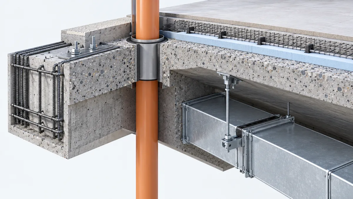
Imagine a duct modeled to design dimensions. Teams may still need to see the supporting arrangement and intended passage through a structural wall to evaluate installation conflicts. Those features may belong in the agreed LOD 350 scope. Their presence is not, by itself, evidence of completed fabrication detailing or site verification.
The exact inclusions differ by element category. An electrical assembly, concrete foundation, and curtain wall do not have identical coordination requirements. Consult the relevant specification entry rather than applying a generic rule that every bracket, fastener, or sleeve must appear everywhere.
How Do LOD 300 and 350 Compare for Foundations and Slabs?
The distinction becomes clearer in concrete work, where geometry and construction interfaces can be specified separately. A foundation element at LOD 300 conveys defined design geometry; the higher level adds selected penetrations and connections. Requirements vary among column foundations, grade beams, and slabs-on-grade, so their entries should not be merged into one universal list.
| Element | LOD 300 example | Additional LOD 350 inclusions |
|---|---|---|
| Column foundation | Design-specified bearing depth, pier top, and pier size | Dowels and couplers |
| Grade beam | Follows the specification's standard-foundation LOD 300 entry | Penetrations, expansion joints, chamfers, dowels, embeds, keyways, and void boxes |
| Slab-on-grade | Overall geometry, thickness, depressions, edge turn-downs, and specified openings | Penetrations at rough-opening dimensions, control and expansion joints, anchors, dowels, and void boxes |
These examples reflect BIMForum's 2025 element entries, not a blanket inventory for all concrete models. In that edition, the slab-on-grade entry places pour joints and reinforcement at LOD 400, so automatically listing them as LOD 350 items would overstate the published requirements.
A wall-to-slab junction gives another practical illustration. LOD 300 may define the general wall and slab accurately; detailed coordination may additionally require a modeled opening or embed. The relevant model author should document both what has been included and what remains outside the agreed scope.
What Can Teams Reliably Do at Each LOD?
LOD 300 supports measuring developed geometry and evaluating general space requirements, while LOD 350 supports more detailed reviews at construction interfaces. Neither designation guarantees a particular cost estimate, construction schedule, or collision-free installation. Those outcomes also depend on coordination procedures, model coverage, the agreed information exchanges, and separate project data.
| Project task | LOD 300 contribution | LOD 350 contribution |
|---|---|---|
| Design documentation | Measures developed element geometry | Adds construction-interface context where required |
| Clash review | Identifies conflicts among modeled primary elements | Reviews interactions involving modeled connections and penetrations |
| Quantity takeoff | Allows quantities from the objects represented | May include additional measurable coordination components |
| 4D planning | Can supply geometry linked to schedule activities | Adds interface information, but does not itself certify sequencing |
BIMForum developed the specification with quantity takeoff, 3D coordination, and 3D control or planning in mind. That background does not establish guaranteed scheduling capability at one LOD. A 4D result depends on how activities are defined, linked, and maintained.
Where Does LOD 350 Sit Relative to LOD 400 and 500?
LOD 350 lies between developed design geometry and fabrication-oriented modeling. LOD 400 requires information sufficient for fabrication, assembly, and installation, often comparable to shop-drawing development. LOD 500 is different: it describes an existing or constructed condition based on observation, verification, or inference, with the accuracy explicitly stated.
A steel connection requiring shop fabrication might progress beyond coordination-level representation to the bolt, plate, and assembly information specified for manufacture. That does not mean the entire building must reach LOD 400. Many deliverables intentionally mix levels according to discipline responsibilities and construction milestones.
Crucially, LOD 500 is not a promise of greater geometric detail than LOD 400. It changes the basis of the representation from proposed work to an observed condition. The record should say how accuracy was determined, particularly when parts are hidden or inferred rather than directly measured.
Which Level Should Your BIM Execution Plan Specify?
Specify LOD 300 when a model element needs developed design geometry, and choose LOD 350 when its physical relationships must be modeled for detailed coordination. Make the decision for each element and milestone rather than demanding one LOD for an entire project. Record ownership, acceptance checks, and exclusions so model users understand what can be trusted. A BIM execution plan template gives these decisions a consistent structure.
- Identify the deliverable: design review, coordinated installation planning, fabrication, or existing-condition documentation.
- List the elements that affect the intended decision, such as ducts, slabs, grade beams, equipment, and structural supports.
- Define what is measurable at the required level, including any specific openings, embeds, or connections.
- Name the model element author, due milestone, exchange format, and review responsibility.
- Document unresolved interfaces and items represented only in 2D notes, rather than silently treating them as modeled.
The practical difference between LOD 300 and 350 is whether the next coordination decision needs information beyond an element's designed geometry. Use the applicable BIMForum edition and the project's LOD matrix to define that extra information. Higher LOD is useful when it serves a clear purpose, not simply because it is a larger number.