Construction drawings
Building Construction Detail Drawings: Types, Scales, and Where They Fit in a Set
Building construction detail drawings are large-scale drawings of individual building parts - a wall assembly, a window opening, a column base - that carry the dimensions, materials, and connections needed to build that part correctly. They show the finest and most intricate information about how a specific piece of the building goes together, down to individual layers and connections, and they sit within the broader construction set alongside foundations, walls, elevations, cabinetry, MEP design, structural details, and ceiling plans.
This article sorts the common detail types - exterior wall and window details, foundation and structural details, assembly and component details, MEP details, and fire protection details - and explains what each one documents. It then covers the scales details are drawn at in US practice, traces how details are issued with working drawings, refined as shop drawings, and recorded as as-builts at closeout. It closes with how many details a set realistically needs - one architect counted roughly 63 details for a single exterior wall - and how shop, assembly, component, and as-built drawings relate to the designer's details.
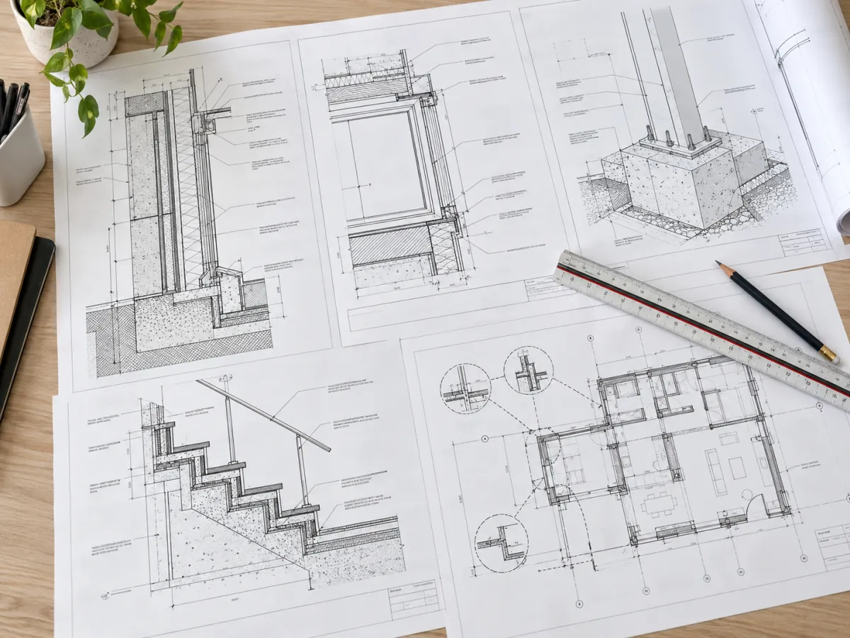
What Are Building Construction Detail Drawings?
Building construction detail drawings enlarge selected building elements, such as wall assemblies, window openings, and column bases, to show how their materials, layers, dimensions, and connections fit together. Unlike a general floor plan, an architectural detail drawing focuses on one construction condition that needs to be communicated at a readable scale.
A detail drawing is distinct in its job: where a floor plan tells you where a wall sits, the wall detail tells you what that wall is made of, in what order the layers stack, and how those layers connect. A wall detail uses a larger scale precisely because it needs to show materials, layers, and connections that a smaller drawing cannot resolve. Details are where the design intent of the construction documents becomes buildable instruction - the point, as one practicing architect put it, of detailing how the building should be built, not just what it looks like.
Within the broader set of construction drawings - the final preconstruction documents that represent the whole building, including foundations, walls, elevations, interior details, cabinetry, MEP design, structural details, and ceiling plans - details are the close-up layer.
How Detail Drawings Differ From Plans, Sections, and Elevations
Plans, sections, and elevations establish the location and overall form of a building, while construction drawing details explain how individual assemblies connect. A plan locates a wall, for example; a wall section drawing or enlarged detail shows the materials and interfaces that a smaller-scale view cannot communicate clearly.
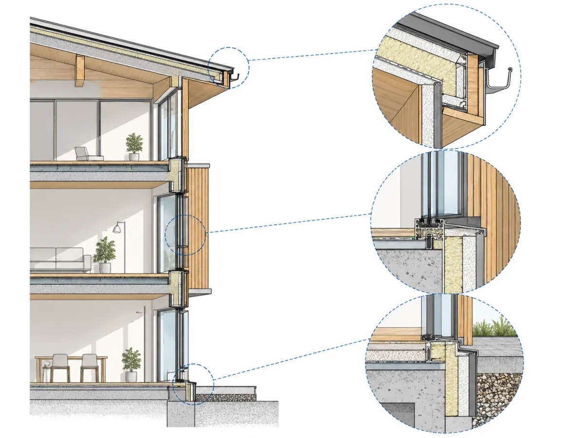
Each drawing type in a set answers a different question at a different zoom level:
- Floor plans show the layout of individual rooms, walls, doors, and windows from above, with room names, dimensions, and fixture placement.
- Elevations show the exterior faces of the building - finished floor levels, window heights, roof pitches, and material transitions.
- Building sections cut through the building to reveal how the foundation connects to the walls and the walls to the roof structure.
- General arrangement (location) drawings establish where things are; architectural drawings specify the general arrangement and background of the facility and are shared with other disciplines for coordination.
- Details take a single junction flagged on any of the above and draw it large enough to show its materials, layers, and connections.
The distinction is fundamentally one of scale and purpose. A scale drawing represents a larger object at a size it can be viewed and comprehended on paper, and each view uses a scale suited to its purpose. Architectural construction details trade broad coverage for a readable explanation of one assembly or junction.
Types of Detail Drawings in a Building Construction Set
Building detail drawings are grouped by the condition they explain: enclosure and window interfaces, foundations and structural connections, component assemblies, MEP installations, and fire protection. Each type identifies relevant materials and relationships at a readable scale. The table summarizes what these architectural and structural detail drawings typically document.
| Detail type | What it documents |
|---|---|
| Exterior wall and window details | How the building enclosure is assembled - insulation layers and exactly how waterproof barriers overlap at windows, doors, and roof valleys |
| Foundation and structural details | How load-bearing elements such as beams, columns, foundations, and walls are constructed, including member sizes, reinforcement, and load requirements |
| Assembly details | How different building components connect and coexist in a shared space, showing the relationship between components in a consolidated view |
| Component details | Detailed information about individual units, drawn at large scales such as 1:10, 1:5, 1:2, or 1:1 |
| MEP details | How mechanical, electrical, and plumbing systems are installed and integrated, including ductwork layouts, wiring and circuit layouts, and pipe and fixture locations |
| Fire protection details | How sprinklers, alarms, and fire-resistant materials are arranged to protect the building and its occupants |
| Flashing and stair details | Exactly how waterproof barriers overlap at windows, doors, and roof valleys, plus precise stair rise, run, handrail heights, and attachments |
One caution applies across all of these: standard architectural detail drawings for door frames, window frames, fireproofing, and material connections exist, but they must be adapted to the particular building. Where conditions genuinely differ, a "typical" detail misleads - the designer needs to understand the construction well enough to detail each unique situation accurately. A typical detail drawing should therefore state where it applies and where an exception needs its own detail.
What Scale Are Construction Detail Drawings Drawn At?
Construction detail drawings usually use larger scales than floor plans so material layers and connections remain legible. In US architectural practice, enlarged details may use 1-1/2 in = 1 ft or 3 in = 1 ft, depending on complexity. The table shows common imperial scales and their applications.
The common US imperial scales and their typical uses:
| Scale | Ratio | Common use |
|---|---|---|
| 3 in = 1 ft | 1:4 | Small details |
| 1-1/2 in = 1 ft | 1:8 | Small details |
| 1 in = 1 ft | 1:12 | Small details / construction details |
| 3/4 in = 1 ft | 1:16 | Construction details / wall sections |
| 1/2 in = 1 ft | 1:24 | Building sections |
| 3/8 in = 1 ft | 1:32 | Wall sections / building sections |
| 1/4 in = 1 ft | 1:48 | Building sections / floor plans / elevations |
| 1/8 in = 1 ft | 1:96 | Floor plans / elevations / site plans |
| 1/16 in = 1 ft | 1:192 | Site plans |
The pattern is consistent: a smaller area can be shown at a larger scale, leaving more room to explain materials and connections. Scale choice also depends on the size of the assembly, required detail, sheet size, and drawing purpose. The imperial conventions shown here are common in US construction documentation, while metric projects use their own scale conventions.
How Detail Drawings Are Used From Design Through Closeout
Construction details move through a project in several forms. The issued drawing set communicates intended assemblies; shop drawings develop selected fabrication or installation information; field review checks applicable conditions; and as-built records document reported or verified changes after installation. These stages serve different purposes, even when they describe the same component.
- Issued with the working drawings. Details accompany the construction set to communicate dimensions, materials, and intended connections across disciplines. Their purpose is to resolve as many assembly questions as practical before construction begins, while the available design options are still broad.
- Coordinated with trade partners. The set is shared so disciplines can review interfaces against the same design information. On renovation and retrofit work, point-cloud data can inform construction details during design and support checks against observed conditions; it does not automatically verify every concealed assembly.
- Developed into shop drawings where required. Contractors, subcontractors, and fabricators prepare shop drawings for selected fabricated or prefabricated components, subject to the project's submittal and review process.
- Documented at closeout. Contractors and trades commonly provide records of installed changes for as-built drawings. The completed documents support maintenance and renovations, but their completeness and accuracy depend on the evidence and checks required by the project.
How Many Details Does a Drawing Set Need?
There is no universal number of construction details required in a drawing set. The amount depends on distinct junctions, repeated assemblies, project complexity, and how clearly the work must be communicated. One architect described roughly 63 details for a single exterior wall, illustrating why detail counts vary considerably.
That 63-detail count came from a residential project where the building enclosure was, in the architect's words, the real meat and potatoes of the job: window details 1, 2, and 3 had been modified to add a layer of 1 in rigid insulation board, and more details were on the way. The point was not volume for its own sake; the same studio's 4,440 sq ft house was documented across 42 E-size sheets, and a pricing review stopped at least 6 more sheets of interior details from being added. Practice varies widely: the author compared a 25-page residential set prepared by a newly hired architect with his own set for a similarly sized house, which he described as over 800% larger.
The rationale is practical, not perfectionist. Where important assembly conditions are left unresolved, the team may face fewer options once related work is installed. Clear, project-specific detail drawings help communicate intended solutions early, although field coordination and appropriate submittal reviews remain necessary.
How Shop, Assembly, Component, and As-Built Drawings Relate to Details
Shop drawings, assembly drawings, component drawings, and as-built drawings relate to construction details but are not interchangeable. Shop drawings develop contractor or fabricator information; assembly and component drawings explain how parts fit together; and as-built records describe reported or verified installed conditions. Their purposes and preparation stages explain the difference.
- Shop drawings are prepared by contractors, subcontractors, or fabricators to develop fabrication and installation information for particular components, such as MEP assemblies or cabinetry. Their review follows the project's specified submittal procedure.
- Assembly drawings depict the connection and relative position between different components of the structure when components come together in a shared space, using various types of details and references for a consolidated view.
- Component drawings provide detailed information about individual units, typically drawn at large scales such as 1:10, 1:5, 1:2, or 1:1; components are generally self-contained and sourced from a single supplier.
- As-built drawings document reported or verified installed conditions, including deviations from construction drawings. Contractors and subcontractors commonly supply field records, and the final compiler depends on project requirements. Unverified or concealed conditions should not be presented as independently measured facts.
Together these drawing types sit at different points on the same detail-level spectrum: the design-side details define intent, the fabrication-side shop and component drawings define manufacture, and the as-builts record what was actually built.