Construction drawings
What Type of Drawings Show How Each Wall Is Constructed? Wall Sections Explained
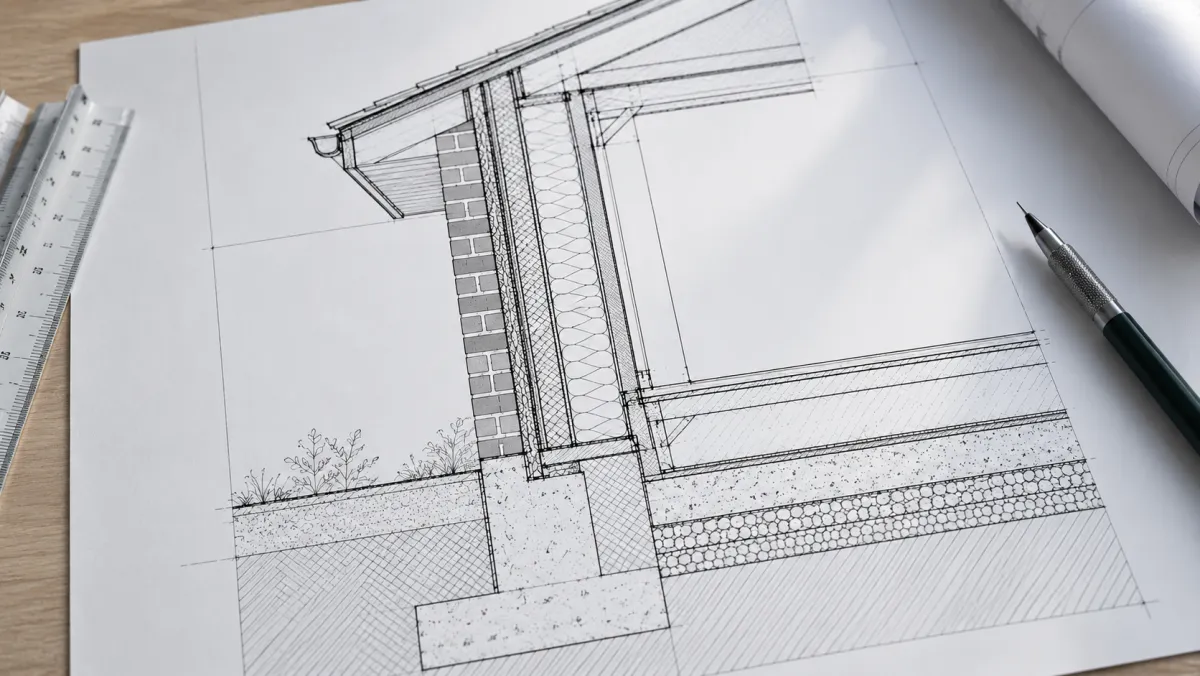
What type of drawings show how each wall is constructed? Wall sections are the primary drawings for showing how a wall assembly is built. They cut through the wall to reveal framing or masonry, insulation, sheathing, finishes, and junctions with floors and roofs. Enlarged wall details explain specific connections, while structural sections document the load-bearing requirements where relevant.
This guide compares wall sections, building sections, structural details, and elevations, including drawing scales and how to follow references across a set. These views work together; no single sheet contains every construction requirement.
What Are Construction Drawings?
Construction drawings communicate the designed building through coordinated plans, sections, elevations, details, and schedules. They identify dimensions, locations, assemblies, and technical requirements at scales suited to their purposes. To understand a wall, readers usually need more than its floor-plan outline: the wall-type reference and related sections explain how the assembly is intended to be constructed.
Floor plans locate walls; elevations show appearance. Sections and details explain layers and junctions; structural sheets add engineered requirements. Specifications may define materials and installation criteria.
Confirm the drawing issue and wall type. Do not apply a generic detail to a different assembly without confirmation.
Which Drawing Types Show How Walls Are Constructed?
Wall sections and wall details are the most direct sources for wall assembly information. General building sections provide broader vertical context, and structural sections address structural components and connections. Elevations are useful for exterior appearance but do not normally reveal a complete wall buildup. The following categories describe related views rather than a fixed number of official drawing types.
| Drawing type | Main information | Where to look |
|---|---|---|
| Building section | Vertical relationships between floors, roofs, and walls | Architectural section sheets |
| Wall section | Wall layers and their connections from base to top | Architectural wall-section sheets |
| Wall detail | Enlarged junction, opening, or transition | Referenced detail sheets |
| Structural section | Engineered framing, reinforcement, and load-bearing connections | Structural drawing set |
| Elevation | Wall face, openings, finishes, and height references | Architectural elevation sheets |
Scale depends on legibility. One practitioner reports using 3/4 in = 1 ft for wall sections; this is not universal. Enlarged details may use 1-1/2 in = 1 ft or 3 in = 1 ft.
What Does Each Wall-Construction Drawing Type Show?
Different construction drawings answer different questions about the same wall. Building sections show the assembly in the context of the structure; wall sections focus on its layers and interfaces; enlarged details resolve local conditions. Structural documents supplement these views where load-bearing elements are involved. Elevations help identify exterior treatments without replacing a cut-through drawing.
What Does a Building Section Show?
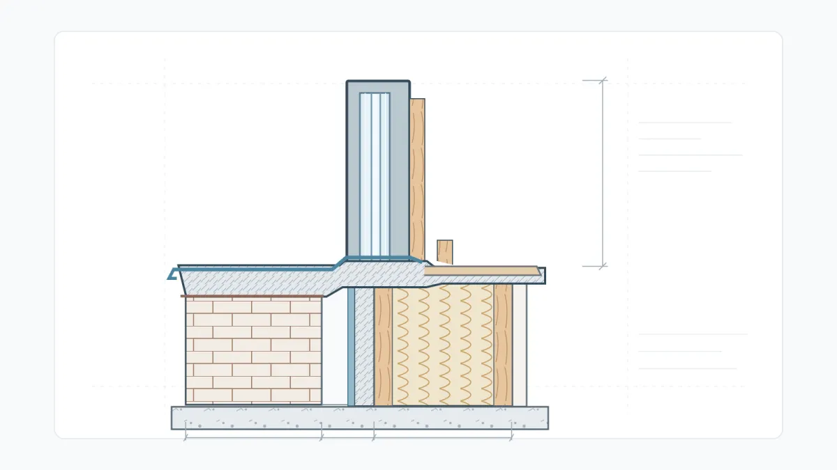
A building section shows the structure as a vertical cut, revealing relationships between floors, walls, roofs, and occupied spaces. It helps readers understand heights, structural alignment, and where important assemblies meet. Although it may include material notes, it does not necessarily show every layer or fastening detail at a scale suitable for construction.
For example, a two-story building section locates floor and roof junctions. A wall-section callout can direct readers to the assembly detail.
What Is a Wall Section Drawing?
A wall section is a focused vertical cut through a wall assembly, showing the designed arrangement of structure, protective layers, insulation, and finishes. It can clarify how that wall meets the foundation, floor, and roof. The drawing should be read with wall-type notes and specifications rather than treated as a complete installation manual by itself.
Different wall types may need separate sections: masonry, framed exteriors, and interior partitions do not share identical layers.
What Does an Enlarged Wall Detail Show?
A wall detail isolates a junction or feature that needs more explanation than the main section can provide. Typical subjects include window heads and sills, flashing transitions, roof-to-wall connections, and wall-to-slab interfaces. Larger scales make notes and material relationships easier to read, but the detail must match the actual project condition. Wall details are one group of detail construction drawings, alongside foundation, structural, MEP, and fire protection details.
A detail callout identifies the relevant sheet and drawing. Verify it before applying a typical detail drawing to a unique junction.
When Do Structural Sections Explain a Wall?
Structural sections explain the engineered parts of load-bearing walls and their connections to beams, slabs, and foundations. They may provide member dimensions, reinforcement, anchorage, and design-related notes. They do not usually replace architectural details about waterproofing, insulation, or appearance, so both drawing disciplines may be necessary to understand one wall.
For concrete or masonry walls, consult structural notes for reinforcement, then architectural sections for finishes. Request clarification if they conflict.
Do Elevations Show How a Wall Is Built?
No. An elevation primarily shows a wall's visible face, including openings, material transitions, and vertical dimensions when indicated. It can identify where a finish changes or a window belongs, but it does not usually show the concealed assembly. A wall section or detail is needed to understand how internal layers connect.
Elevations may refer to cladding types or wall tags that lead to detailed documents. They are not construction sections.
How Do Wall Sections, Details, and Plans Work Together?
Read the drawings as a connected set: use a plan to locate the wall, a wall-type tag to identify its assembly, a section to understand its layers, and a detail to resolve critical junctions. Structural sheets and specifications supply complementary requirements. Check references and revisions so information from separate sheets describes the same condition.
For a window, locate the wall type on plan, follow its section marker, then check the head and sill details. Review elevations and structural sheets as needed.
If a typical detail conflicts with an unusual wall buildup, confirm what governs. Design drawings do not verify actual construction.
The practical answer is consistent: wall sections explain the overall construction of a wall, while wall details explain particular connections. Use building sections, structural documents, elevations, and specifications to complete the picture without asking any one sheet to do every job.