Construction drawings
Drawings That Represent a Material or Component on a Plan: Symbols and Hatch Patterns
Drawings that represent a material or component on a plan use graphic conventions rather than full-size pictures. A hatch or filled region can identify a material, while a simplified symbol, tag, or keyed note identifies a building component. These marks gain their meaning from the drawing legend, notes, schedules, and specifications. A concrete wall, door, or electrical device may therefore be represented differently depending on the sheet and project standard.
This guide explains the difference between material hatches and component symbols, where each appears in architectural and engineering drawings, and how to decode an unfamiliar mark without guessing. It includes reference tables for typical materials and components, a five-step reading method, and an example involving an outlet and a wall assembly. It also clarifies when a label, finish schedule, or drawing detail is needed to complete the interpretation.
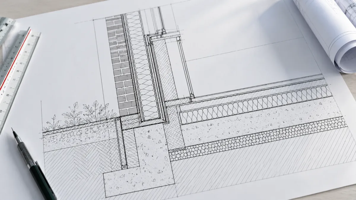
What Represents a Material or Component on a Construction Plan?
The answer is a drawing symbol, but its form depends on what is being represented. Materials may use cut patterns, surface patterns, or finish tags; components may use outline graphics, schematic symbols, or identifiers. Reading the associated legend and notes is necessary because an identical-looking mark can carry different meanings across projects.
For example, an architectural plan might display a door with an opening arc and a tag that refers to a door schedule. An electrical plan may place a simplified receptacle symbol at a wall. A wall section can show differently patterned regions that distinguish material layers without drawing individual bricks or fibers. The plan conveys location; the annotations identify the specified item.
This distinction matters because a material pattern does not always identify a complete assembly. A region associated with concrete, for example, does not tell you reinforcement, compressive strength, or fire rating unless those properties are specified elsewhere. Likewise, a fixture symbol is not a substitute for its mounting height, circuit designation, or product schedule. Drawing graphics are a navigation system for technical information, not a replacement for it.
What Types of Symbols Appear on Architectural and Construction Plans?
Construction plan symbols fall into two practical categories: material representations and component or equipment representations. A hatch identifies a patterned region, while a component symbol indicates an item or device at a particular position. Drawing tags, leader lines, abbreviations, and schedules provide further identification when the graphic alone is insufficient for construction.
Architectural drawing symbols appear alongside dimensions, grid lines, room names, and drawing references. Different disciplines organize them differently: a reflected ceiling plan focuses on overhead elements, whereas an electrical sheet emphasizes devices and circuits. Start by determining which drawing and discipline you are reading before interpreting any symbol. A mark used on one sheet should not be assigned the meaning of a similar mark from another without checking its definition.
How Do Material Hatch Patterns Identify Building Materials?
Material hatch patterns use repeated lines, marks, or fills to distinguish regions of a drawing. They can indicate materials in cut views or represent surface finishes, depending on the view settings. There is no guarantee that a particular hatch appearance means the same material everywhere, so confirm its meaning in the project documents.
| Material or finish | Where it may appear | What to verify |
|---|---|---|
| Brick masonry | Wall sections and enlarged wall details | Wall type, material designation, and specification |
| Concrete | Foundation plans, sections, and structural details | Element type, notes, and structural references |
| Concrete masonry units (CMU) | Wall plans, sections, and assembly details | Wall schedule, reinforcement, and assembly notes |
| Wood | Framing details, architectural sections, and finish plans | Structural or finish designation and member size |
| Insulation | Wall and roof sections | Product type, location, and thickness notes |
| Earth or backfill | Site or foundation sections | Grade lines, backfill notes, and civil references |
| Tile or other finish | Finish plans, elevations, and schedules | Finish code, extent, and material schedule |
A CAD hatch library may offer predefined industry-style patterns and custom alternatives. The library name is not proof that the graphic has an identical meaning in every office. The drawing author may also change pattern scale or display settings, making the same material look different on different sheets. If a surface finish is identified only by a code, consult the finish schedule rather than inferring the product from its linework.
Material symbols in construction drawings should also be checked against the actual view. A cut section reveals the materials through which the cutting plane passes; an elevation primarily shows visible surfaces. An unpatterned region is not automatically an unbuilt or empty space. At smaller scales, material patterns may be omitted for legibility while notes and wall-type references carry the detailed specification.
Which Component Symbols Are Common on Building Plans?
Component symbols stand for discrete items such as doors, plumbing fixtures, lighting equipment, and electrical devices. Their graphics may resemble the item, use an abstract schematic mark, or consist only of an identifier. Because conventions vary by discipline and office, the safest method is to connect the symbol to the corresponding legend, schedule, or note.
| Component | How it may be identified | What to check next |
|---|---|---|
| Door | Opening geometry and door tag | Door schedule, swing, and clearances |
| Window | Opening mark or window identifier | Window schedule and elevations |
| Electrical receptacle | Device glyph or receptacle tag | Device legend, mounting notes, and circuits |
| GFCI receptacle | Device marking with GFCI abbreviation when shown | Device schedule or specification; do not infer code compliance |
| Switch | Switch symbol or tagged device | Switching arrangement and circuit notes |
| Light fixture | Ceiling or electrical symbol with fixture type | Lighting schedule and mounting details |
| Junction box | Electrical symbol or keyed identifier | Connection and installation notes |
| Thermostat | Controls symbol or equipment tag | Control sequence and mounting location |
| Plumbing fixture | Fixture outline or tag | Plumbing plan and fixture schedule |
| Supply or return air device | Mechanical device mark with type identifier | Airflow schedule and mechanical notes |
| Equipment | Outline or equipment tag | Equipment schedule, access requirements, and connections |
Common abbreviations may include AFF for above finished floor, FD for floor drain, or GFCI for ground-fault circuit interrupter. However, other abbreviations are project-dependent, and a short code can have different meanings between trades. Read the abbreviations list and the discipline notes. A leader line is one method of linking a note to an element, but not every symbol uses a leader; many rely on tags or schedules instead.
Where Do Material and Component Symbols Appear in a Drawing Set?
The same building information is communicated through several kinds of sheets, and the chosen graphic depends on the view. Floor plans locate components, sections reveal relationships through assemblies, and details enlarge junctions. Finish plans and reflected ceiling plans emphasize other information. Do not expect the same degree of material detail on every sheet.
| Drawing or view | Main purpose | Typical symbol use |
|---|---|---|
| Site plan | Locate the building and site features | Access, landscape, utility, and site identifiers |
| Architectural floor plan | Show spatial arrangement and openings | Doors, windows, wall types, and fixture tags |
| Building section | Reveal vertical building relationships | Cut materials, levels, and assembly references |
| Enlarged detail | Explain a selected connection or construction condition | Patterned material layers, keynotes, and component tags |
| Structural drawing | Describe framing or foundation requirements | Member marks, reinforcement notes, and section references |
| Reflected ceiling plan | Locate ceiling elements | Luminaires, diffusers, sprinklers, and ceiling finish notes |
| Electrical drawing | Identify power and lighting devices | Receptacles, switches, circuit and fixture identifiers |
| Mechanical or plumbing plan | Coordinate building services | Equipment tags, piping, ducts, and fixture labels |
| Finish plan or schedule | Identify specified surface treatments | Finish codes, material tags, and keyed locations |
The distinction between floor plans and sections is especially important. A wall might appear as an outline in plan and as layered construction in a detailed section. You cannot reliably determine its insulation, structural makeup, or weatherproofing by studying the plan outline alone. Follow the wall-type marker or section callout to the document that provides those details. Wall section drawings are the primary source for that layered buildup.
A reflected ceiling plan may also use an abbreviated fixture symbol that looks unlike the physical equipment. Light fixture tags often correspond to schedules containing the fixture type and specifications. Mechanical outlets and sprinklers may be shown nearby but governed by different engineering information. Each mark should be interpreted in its own discipline context, not as a universal architectural symbol.
How Do You Read an Unfamiliar Symbol on a Plan?
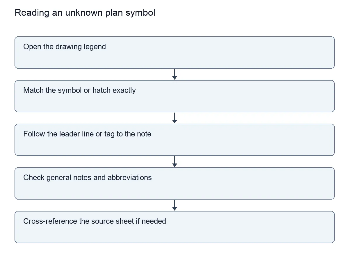
Begin by identifying the current sheet and consulting the applicable symbol legend or abbreviation list. Match the graphic or tag, then follow any leader, keynote, or schedule reference. Finally, cross-check dimensions, mounting information, and related details. If the meaning remains unclear or documents conflict, request clarification instead of guessing from visual similarity.
- Check the sheet identity. Read the title block, discipline, issue date, revision, scale, and view title. Confirm that you are using the current authorized issue.
- Find the relevant legend. Look on the same sheet or the applicable general or discipline legend sheet. Match the symbol, hatch, or abbreviation, including any extra letters or markers.
- Follow attached annotations. Read the device tag, keynote number, leader line, or adjacent text. A graphic may only indicate the location while the note identifies the technical requirement.
- Open the linked schedule or detail. A door tag may send you to a door schedule; a wall-type marker to an assembly schedule; a fixture tag to a lighting or plumbing schedule.
- Resolve inconsistencies. Compare specifications, drawing revisions, and related views. If two controlled documents disagree, follow the project's request-for-information or clarification procedure.
Consider an unfamiliar outlet symbol on an electrical plan. Rather than assuming it is a particular receptacle type, inspect the electrical legend and look for an adjacent annotation such as GFCI. Confirm the device's specified type, mounting information, and circuit references in the notes. A symbol's appearance alone cannot establish where a special device is legally required; that depends on applicable codes, design requirements, and the project context.
Now consider a patterned strip in a wall section. The hatch might be part of an insulation, masonry, or finish representation. Use the material legend and wall-type note to identify the intended layer. Then check the section or enlarged detail for position and thickness, and the specification for product characteristics. This is why reading blueprint symbols involves more than memorizing a catalog of icons.
When reviewing a printed or exported PDF, zoom and line weight can change how symbols appear. An icon may also be simplified in a small-scale view and more detailed in an enlarged plan. Confirm the drawing scale and use written dimensions and schedules rather than measuring a symbol as though it were a full-size depiction of the equipment.
What Determines the Meaning of a Plan Symbol?
The applicable legend and associated project documentation determine how a symbol should be interpreted. Material patterns, device marks, and abbreviations may follow familiar conventions, but their appearance alone is not sufficient evidence. Read the current sheet's legend alongside the relevant notes, schedules, and specifications, especially when two documents appear inconsistent.
A legend is not the same as a title block. The legend identifies graphical conventions; the title block identifies information about the drawing issue and project. In larger construction sets, symbols may be explained on a separate general-notes sheet or a discipline-specific sheet. A key plan, door schedule, material schedule, and specification perform different tasks, even when each helps decode the same graphic.
One useful rule is to treat the drawing as a linked information system. Use graphic marks to find the right object or material, tags to identify its type, and notes or schedules to obtain the properties needed for a decision. Verify that the sheet has not been superseded. When plans, notes, and specifications disagree, document the inconsistency for the design team rather than assigning arbitrary priority.
In short, drawings that represent a material or component on a plan rely on an understandable visual language: hatch patterns for materials, symbols for objects, and annotations for technical meaning. The best readers do not guess a material from a familiar-looking hatch or a device from its shape. They verify the mark against the current project documentation before using it for construction.