Construction drawings
Types of Architectural Drawings: What Each Drawing Shows and Where It Fits
Types of architectural drawings include site plans, floor plans, elevations, sections, and enlarged details, with excavation and landscape sheets added when the project requires them. These documents communicate different aspects of a building, from its location on a property to its spatial arrangement and construction connections. They are coordinated rather than interchangeable.
This guide explains the major architectural drawing types, the information each view communicates, and where it belongs in a drawing set. It also covers typical scales for construction details and explains how design drawings become coordinated working documents during a project. The comparison table makes the distinctions easy to identify before examining their practical uses.
What Is an Architectural Drawing?
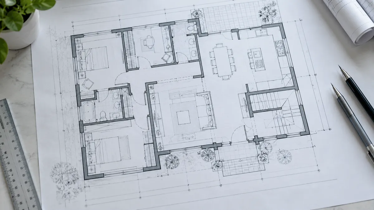
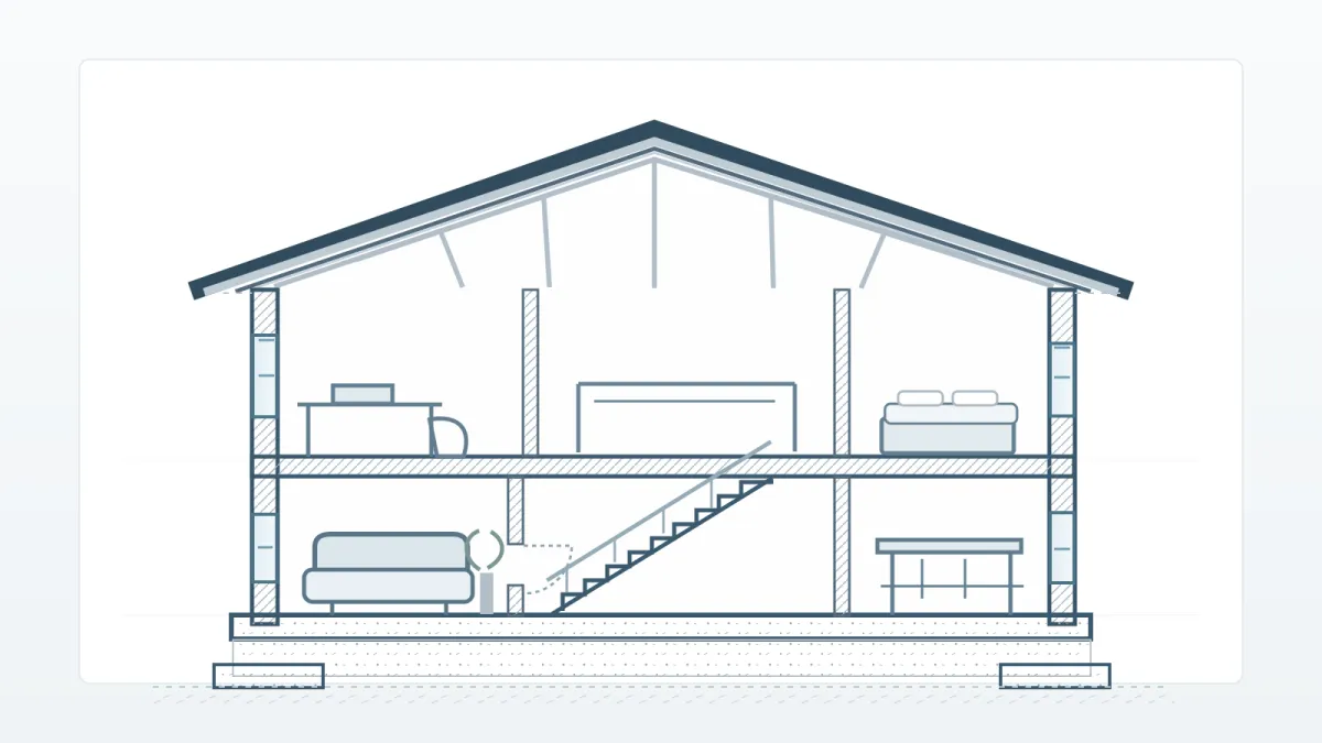
An architectural drawing is a graphic document used to describe a building's design or documented condition. Depending on the view, it may communicate the layout of spaces, the exterior of the building, its vertical relationships, or a selected construction detail. Architectural plans, elevations, and sections work together to explain information that one view cannot show alone.
Technical architectural drawings may also contain dimensions, notes, material indications, levels, and references to related sheets. Their content and level of detail vary with the project stage and the purpose for which a drawing is issued. A presentation sketch, a permit sheet, and an issued-for-construction drawing should not be assumed to have the same status.
What Is the Purpose of Architectural Drawings?
Architectural drawings communicate design intent so project teams can review, coordinate, and construct the proposed building. Different views address different questions: plans organize spaces, elevations communicate exterior appearance, and sections explain vertical relationships. Drawings also support coordination with engineering information, while permit and contractual roles depend on how the documents are issued and used.
For example, a contractor may use a floor plan to locate openings, then consult a building section to understand how floor and roof levels relate. A larger-scale detail can clarify the junction between a wall and a window. Not every architectural drawing is automatically a legal approval or a complete installation instruction.
What Are the Main Types of Architectural Drawings?
The main types of architectural drawings are site plans, floor plans, elevations, sections, and construction details. Additional site-related drawings may cover excavation or landscape work when required. Working drawings are different: they refer to a coordinated production set rather than one particular view. The table shows what each document communicates and its role in the project.
| Drawing type | What it documents | Where it fits |
|---|---|---|
| Site plan | One of the core drawing types in a set, alongside floor plans, sections and elevations | Carries a specific purpose within project-wide communication |
| Floor plan | Supports spatial arrangement documentation | One of the core drawing types in a working set |
| Elevation | Supports aesthetics documentation | One of the core drawing types in a working set |
| Section | At large scale, a standard way of showing building construction details | Typically shows complex junctions that cannot be clearly shown on a drawing that includes the full height of the building |
| Detail drawing | A small part of the construction at larger scale, showing how component parts fit together | Resolves complex junctions such as floor-to-wall junctions, window openings, eaves and roof apexes |
| Excavation drawing | Proposed and existing contours, excavation areas, grading, filling and underground utilities | Guides contractors in planning earthwork operations on site |
| Landscape drawing | Design and arrangement of outdoor spaces: trees, walkways, patios and site furnishings | Created alongside grading, irrigation, drainage and site lighting drawings to guide on-site work |
| Working drawings | The full production set, subdivided into location, assembly and component drawings | Include architect's drawings plus structural and other engineering drawings used to build |
Site and landscape information may be produced with civil engineers or landscape architects, depending on project scope. A coordinated drawing set can also include structural, mechanical, electrical, and plumbing documents, but those discipline drawings are not all architectural views. The separate guide to “what are MEP drawings” covers their types, symbols, and coordination workflow.
Which Scales Do Detail Drawings Use?
Construction details use larger drawing scales than general building plans to make small junctions and components legible. In metric practice, examples include 1:10 and 1:5, with 1:1 reserved for suitable small details. The chosen scale depends on the assembly, sheet size, and amount of information that must be communicated clearly.
For example, a window-to-wall junction may require an enlarged section to show layer transitions and connections, while a floor plan shows only the location of that window. Architectural detail drawings and building sections can complement each other: the section establishes the overall relationship, and the detail explains a specific condition. Imperial detail scales are listed in the guide to building construction detail drawings.
How Are Architectural Drawings Used During a Project?
Architectural drawings support a project from initial design through review, coordination, construction, and record keeping. Preliminary plans and elevations present the design; later working drawings coordinate the information needed for construction. Revised issues communicate authorized changes, while field records document installed deviations. Responsibility for acceptance and closeout depends on the project requirements.
During construction, teams use the current issued drawing set rather than an earlier concept sheet. A site plan can establish location context, floor plans set out spaces, and details clarify assemblies. Excavation and landscape drawings contribute when those activities are included. The drawings should be read together, with their revision status checked before work proceeds.