Construction drawings
Which Type of Construction Drawing Should You Look at First? A Practical Reading Order
Which type of construction drawing should you look at first? After checking the cover sheet and drawing index for the current issue, begin with the site plan. It places the building within its property, showing how access, boundaries, and utility routes relate to the proposed work. For an initial overview, continue through foundation plans, floor plans, elevations, sections, and construction details.
This guide explains how to read construction drawings in order, what to verify on each sheet, and when trade-specific coordination documents take priority. The six-step sequence is a useful orientation method rather than a mandatory sheet order for every project. Always check the drawing register, issue status, and applicable instructions before using any drawing for construction.
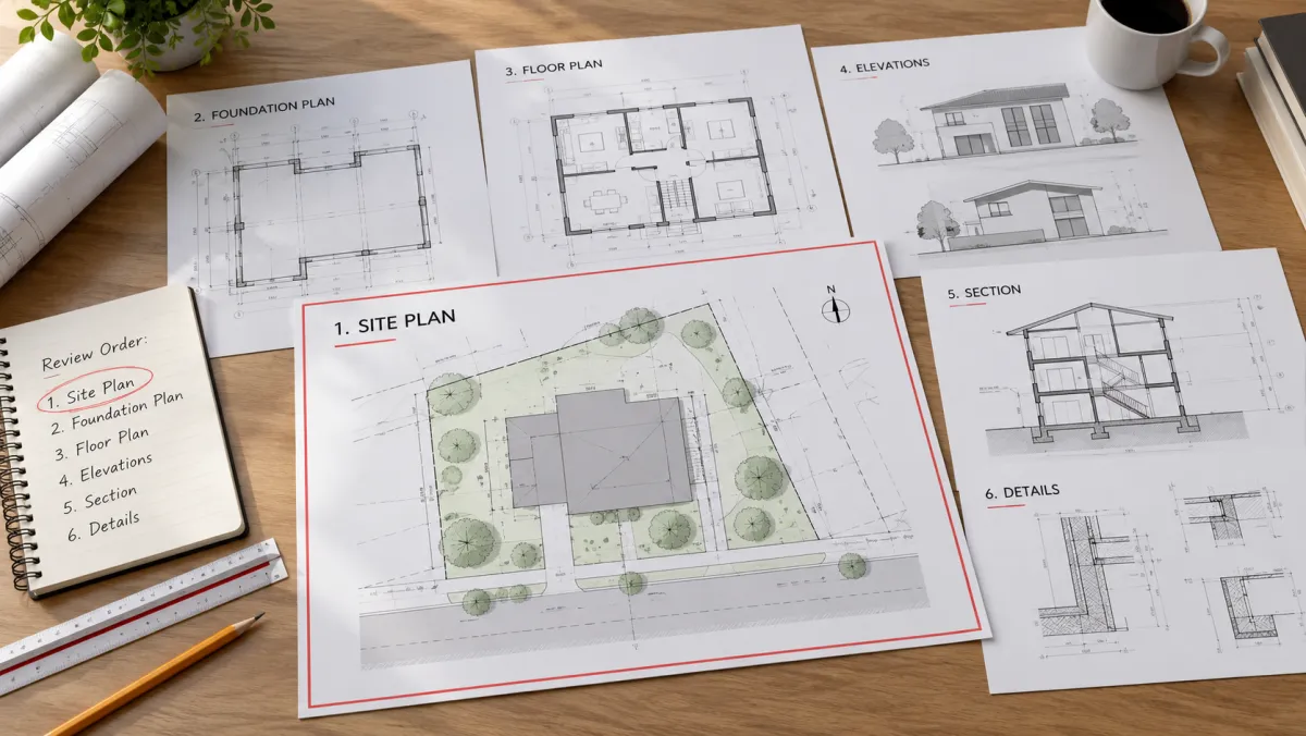
Which Drawing Do You Look at First?
For a first pass through the technical views, start with the site plan. It establishes the building footprint within the property and identifies surrounding conditions that may affect access, drainage, or utility connections. Confirm the drawing index and revision status first, because an outdated site plan can give a misleading starting point.
A site plan gives context that a floor plan cannot provide on its own. You can see where the project sits relative to property lines, roads, nearby structures, and site features, depending on the sheet's scope. This is especially useful when a drawing package contains several buildings, access points, or external utility connections.
The distinction between the first document and the first drawing view matters. Check the cover or index sheet to identify the current set and discipline references. Then use the site plan to orient yourself geographically. If your immediate job involves a specific footing or equipment room, move to that relevant structural or MEP sheet after confirming the overall context.
What Order Do You Read the Rest of a Construction Drawing Set?
After the site plan, a useful general reading order is foundation plans, floor plans, elevations, building sections, and enlarged details. This sequence moves from location and supporting elements to room arrangements, vertical relationships, and individual construction junctions. It is a practical learning order rather than an official rule governing sheet numbering.
| Order | Drawing Type | What It Shows |
|---|---|---|
| 1 | Site plan | The building's location on the site, property lines, and utilities |
| 2 | Foundation plan | The layout and dimensions of the building's foundation, part of the structural drawings that cover load-bearing elements like beams, columns, walls, and floors |
| 3 | Floor plans | The arrangement of rooms, walls, doors, and windows on each level, cut through the building at about 4 ft above the ground to capture windows and doors |
| 4 | Elevations | A vertical view highlighting exterior finishes, siding, and facades |
| 5 | Sections | Cutaway views revealing the building's internal structure |
| 6 | Details | Zoomed-in views of specific components and connections, such as how two materials meet |
Use the table as a reading route, not a substitute for the actual drawing list. A real construction set may group architectural, structural, civil, mechanical, electrical, and plumbing sheets by discipline. Its numbering sequence may therefore differ, and some projects have multiple foundation or floor plans.
For example, a floor plan identifies a window opening, an elevation shows its height and exterior position, a section explains its relationship to the wall and floor, and a detail may explain the frame-to-wall junction. Reading across these views helps you understand one condition without assuming a single sheet contains every construction instruction. Each of these types of architectural drawing communicates a different aspect of the same building.
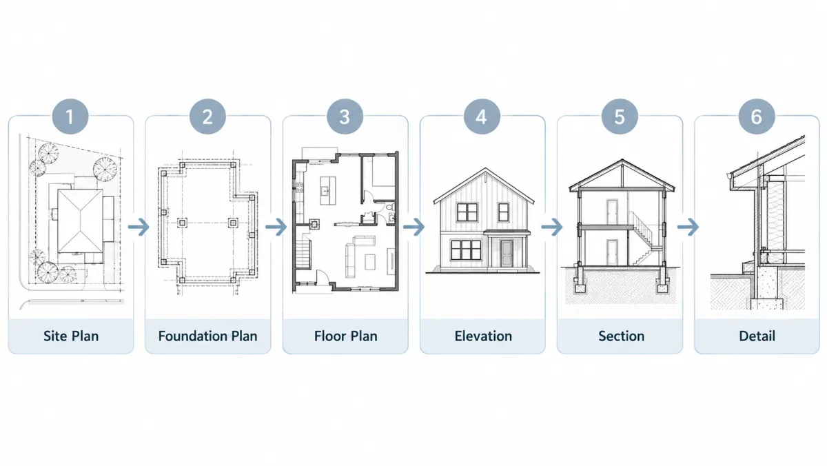
If you are learning the order to read construction drawings, treat cross-references as part of the process. Follow section markers, detail callouts, and schedule tags to their corresponding sheets. Where documents disagree, do not choose the more convenient view; follow the project's clarification and revision procedure.
What Should You Check on Each Sheet Before Reading It?
Before interpreting a construction drawing, check the title block, issue date, revision information, view scale, and referenced notes. These controls identify whether the sheet is relevant and current. A clear drawing can still be unsafe to rely on if it belongs to a superseded issue or carries unresolved changes.
- Title block and drawing index. Identify the project, sheet number, drawing title, discipline, issue purpose, and date. Compare the sheet with the current index or transmittal; formats differ, so not every title block contains the same fields.
- Revision history and change markings. Read revision numbers, dates, descriptions, and any revision clouds. Clouds can highlight modified areas, but not every revision is necessarily clouded. The latest controlled issue is more reliable than cloud markings alone.
- Scale and written dimensions. Check the view scale, sheet size, and print settings. When marked NTS (not to scale), do not obtain measurements by scaling the graphic. Even on scaled drawings, rely on verified written dimensions rather than guessing a distance from an image or a resized PDF.
Next, read the legend, general notes, keynotes, section references, and schedules relevant to the work. Symbols and line weights follow project conventions; do not assume a heavy line always represents a structural wall. A window tag, for instance, may refer to a schedule that gives the specified type and dimensions. The general notes for architectural drawings often sit on a cover or general-information sheet.
A good construction drawing reading workflow keeps these checks repeatable: identify the sheet, verify its status, understand the view, follow linked details, and raise questions when information conflicts. This is more dependable than memorizing only the order of sheet categories.
Which Drawing Should Trades Prioritize for On-Site Coordination?
For on-site coordination, the most useful drawing depends on the trade's immediate task. A sequencing or phasing drawing can show which activities occur when, while coordinated shop drawings and discipline plans clarify what each crew installs and where. Start with current, approved information for the specific work package, not one universal trade drawing.
A foundation crew may need structural foundation plans, site levels, and underground-utility references. An HVAC installer may compare mechanical plans, sections, equipment clearances, and coordinated shop drawings. A construction sequencing drawing can help multiple trades understand activity dependencies, but it does not replace the technical details required to install a duct, pipe, or connection.
Construction sequencing and spatial coordination answer different questions. Sequencing addresses when and in what order work takes place; spatial coordination addresses where systems fit and whether they interfere. Scheduling documents, installation drawings, and coordination models should therefore be reviewed together when the work requires them.
What Does NBIMS-US Say About MEP Coordination Drawings?
The National BIM Standard–United States, Version 3, includes a practice document addressing MEP and fire-protection spatial coordination for construction installation models and deliverables. It describes collaboration, shared digital information, interference reviews, and responsibilities. This guidance does not automatically govern every U.S. project or replace its contract and project-specific BIM requirements.
Where adopted for a project, the guidance outlines a process in which the design team provides relevant model and drawing references, participating contractors develop coordinated backgrounds, and the team exchanges current files through a shared workspace. Coordination meetings identify spatial interferences and assign responsibility for follow-up changes.
The aim is to support fabrication and installation decisions, not to redefine the entire design-approval process. For example, a clash between a supply duct and a structural beam may require a revised route, a clearance check, and input from the responsible designer. That resolution should be recorded in the project's controlled documents rather than assumed from a model screenshot.
The practical answer remains simple: check the current document index, start with the site plan to understand the building's location, then follow the relevant plans, elevations, sections, and details. Once work moves to a particular trade or construction phase, prioritize the approved discipline and coordination documents for that task.