Construction drawings
MEP Drawing: Types, Symbols, and the Coordination Workflow
An MEP drawing shows how a building's mechanical, electrical, and plumbing systems are designed, located, and connected. MEP drawings include ventilation and air-conditioning plans, power and lighting layouts, water supply and drainage drawings, and related technical information. Each sheet communicates a particular system, while coordinated documents help installers avoid competing for the same physical space.
This guide explains what an MEP drawing contains, how to read its symbols and sheet numbers, which drawing types appear during a project, and when those documents are issued. It also outlines the installation-level coordination process described in NBIMS-US Version 3, including model exchanges, coordination meetings, and documented changes.
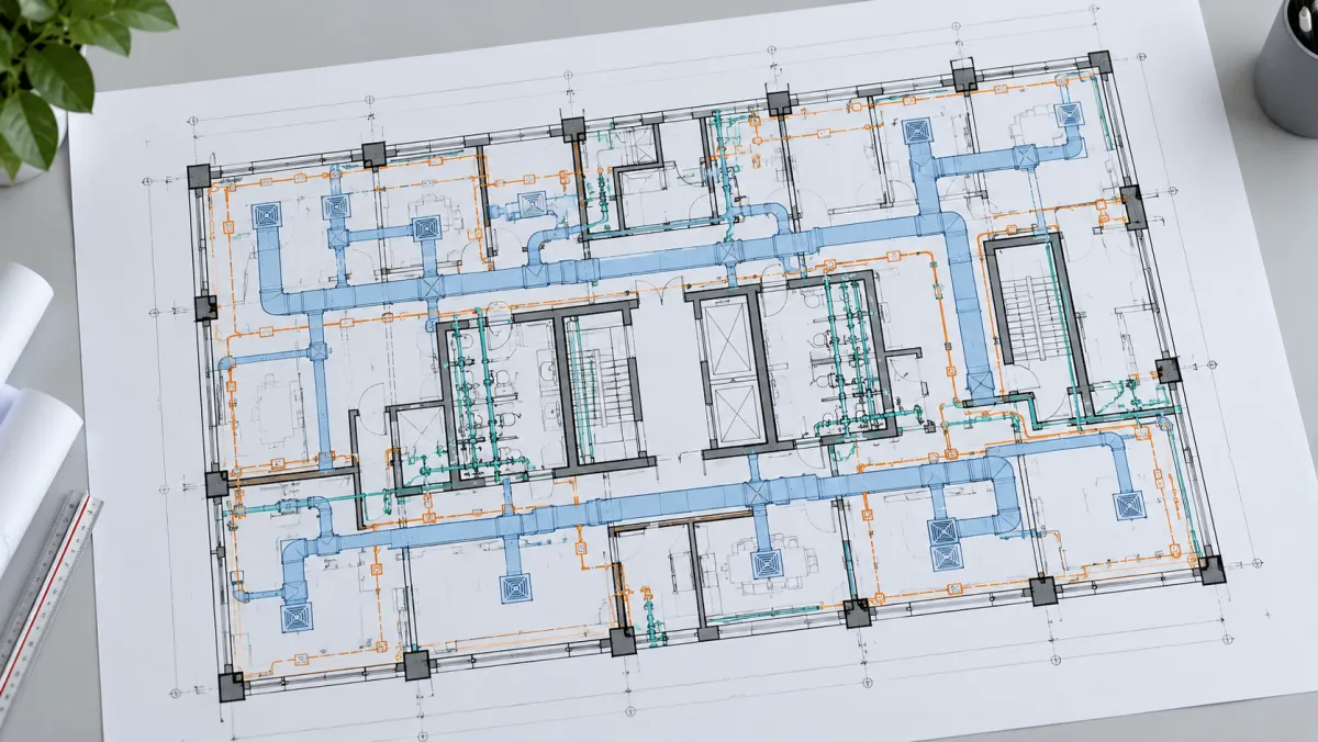
What Are MEP Drawings?
MEP drawings are technical plans, diagrams, and details for a building's mechanical, electrical, and plumbing systems. They communicate routes, equipment, connections, dimensions, and installation requirements at a level suited to their project stage. They are typically read alongside architectural and structural drawings because ducts, pipes, cables, and equipment must fit within the same building. The main types of architectural drawings include site plans, floor plans, elevations, sections, and details.
Mechanical drawings may show ductwork, air-handling equipment, controls, and ventilation arrangements. Electrical drawings describe lighting, power distribution, circuits, and related equipment. Plumbing drawings cover water supply, drainage, fixtures, and applicable piping systems. Fire protection information may be coordinated with the MEP package, although responsibility and sheet organization depend on the project.
A design-stage MEP drawing is not identical to a contractor's shop drawing or an as-built record. Design documents express the proposed installation; shop drawings develop selected fabrication and installation information; as-built documents record reported or verified changes. Checking each sheet's issue status is therefore as important as reading its geometry. The comparison of shop drawings vs construction drawings explains who prepares and reviews each one.
How Do You Read MEP Symbols and Sheet Numbers?
Start with the drawing index, legend, abbreviations, and general notes before interpreting individual symbols. Mechanical, electrical, and plumbing sheets often use discipline identifiers such as M, E, and P, followed by project-specific sheet numbers. A diffuser, valve, receptacle, or pipe symbol should be read against the legend rather than guessed from appearance.
On a mechanical plan, follow duct sizes, airflow arrows, equipment tags, levels, and references to sections or schedules. On an electrical plan, distinguish lighting fixtures from power devices and consult circuit and panel information. On plumbing drawings, check pipe sizes, flow direction, slopes where shown, and riser diagrams. Naming and symbol conventions vary by project, so a sample M-101 sheet number is illustrative, not universal.
Which Types of MEP Drawings Does a Project Use?
A typical MEP documentation package combines discipline drawings with coordination and construction-stage records. HVAC, plumbing, electrical, and sometimes fire protection drawings describe building systems. Coordination, penetration, shop, and spool drawings help teams plan or fabricate installations; as-built drawings capture completed changes. These are useful categories, not nine mutually exclusive sheet disciplines.
| Type | Applications |
|---|---|
| HVAC drawings | Air distribution, energy efficiency, equipment placement |
| Plumbing drawings | Water supply, drainage, gas systems |
| Electrical drawings | Power distribution, lighting, wiring diagrams |
| Fire protection | Fire alarms, sprinklers, safety compliance |
| Coordination | Clash detection, spatial integration |
| Penetration | Block-out and sleeve placement |
| Shop drawings | Fabrication and installation instructions |
| Pipe spool drawings | Prefabrication and construction efficiency |
| As-built drawings | Final state documentation for maintenance |
The categories overlap in practice. For example, a plumbing contractor may issue a coordinated shop drawing and a separate pipe spool drawing for the same system. Similarly, an as-built package may include revised mechanical, electrical, and plumbing sheets rather than a single combined drawing. The required deliverables should be established by the contract and project team.
How Do HVAC Drawings Fit Into an MEP Set?
HVAC drawings form the mechanical portion of an MEP set and describe how heating, ventilation, and air-conditioning equipment connects to air distribution and related systems. Depending on scope, they may include duct plans, mechanical room layouts, schedules, controls, and sections. Their routes must be coordinated with structure, electrical systems, plumbing, and service clearances.
A ceiling coordination review illustrates the need: supply ducts, sprinkler pipes, cable trays, lighting fixtures, and access panels may share limited space. Mechanical drawing details help communicate duct sizes and levels, while combined coordination views expose potential interferences. An HVAC layout alone does not establish that all adjacent systems have been reconciled.
When Are MEP Drawings Produced and What Do They Drive?
MEP drawings develop through design, approval, procurement, construction, and closeout, with different levels of detail at each stage. Early documents establish system concepts; later drawings communicate coordinated locations and installation requirements. Contractors may then prepare shop or fabrication drawings, while field records capture deviations for the final as-built package.
- Concept and design development: Engineers establish equipment needs, preliminary distribution routes, and space allowances in coordination with the architectural design.
- Permit and tender documents: The team issues the applicable technical plans, notes, and schedules for review, pricing, or approval, depending on local and contractual requirements.
- Construction and fabrication: Issued drawings inform installation, while coordinated shop drawings and spool details may develop buildable routes and assemblies.
- Closeout: Contractors commonly record installed changes so owners can use the accepted record set for future maintenance or renovation.
A drawing intended for authority review may not include every fabrication detail. Conversely, a shop drawing is not automatically an approved design revision. Drawing status, revision dates, responsibilities, and required approvals must remain visible throughout the process. This distinction helps prevent teams from using an outdated coordination view as a construction instruction.
What Does NBIMS-US Version 3 Say About MEP Coordination Drawings?
NBIMS-US Version 3 includes a practice document on spatial coordination of mechanical, electrical, plumbing, and fire protection systems for construction installation models and deliverables. It describes team roles, shared files, interference review, meetings, and coordination records. Its scope is installation-level coordination, not a substitute for design coordination or project-specific contracts.
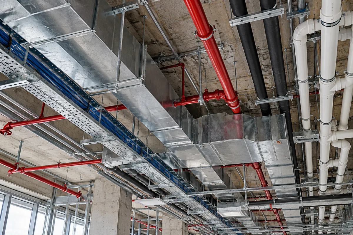
The workflow described in that document can be summarized as follows when adopted for a project:
- Provide design references. The design team supplies the relevant electronic design models and contract drawing files so participating trades can establish a common background, subject to the document's specified exchange requirements.
- Prepare coordination backgrounds. The MEP spatial coordination team develops reference drawings, key plans, and views aligned with the project's drawing conventions. Participants identify the components and access clearances that must be coordinated.
- Maintain shared information. A common electronic workspace is used for current contract files, coordination models, submitted drawings, updates, and comments so teams work from identifiable versions.
- Review spatial interferences. Coordination meetings use combined model views to find conflicts among ducts, pipes, electrical systems, protection systems, and the structure. The responsible party is identified, and design-team input is requested when a conflict requires design decisions.
- Record and distribute changes. The coordinator documents required adjustments after coordination meetings and communicates them to participating trades. Design changes follow the project's established review and distribution process.
This is guidance from a specific NBIMS-US Version 3 practice document, not proof that every building project must follow the same five steps or deliver identical files. NBIMS-US Version 4 now exists, while earlier material remains available for projects that reference it. Always check the governing agreement, current project BIM requirements, and applicable authority procedures before treating a coordination deliverable as mandatory.