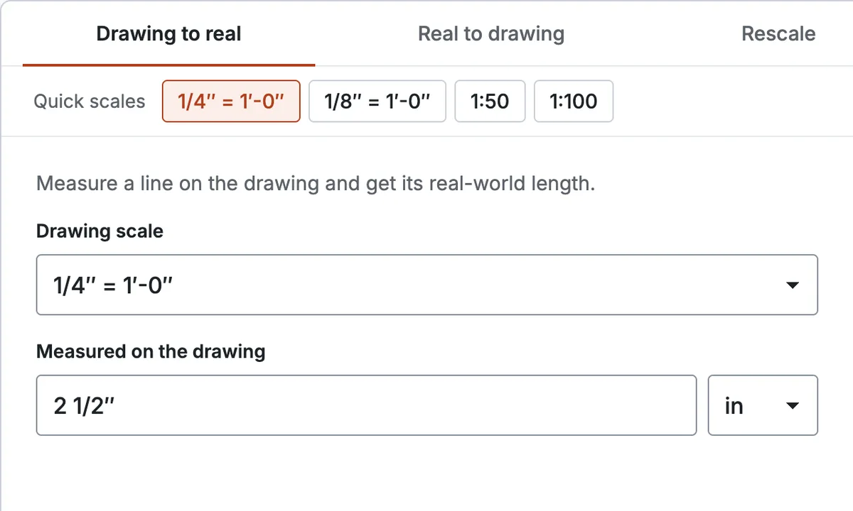
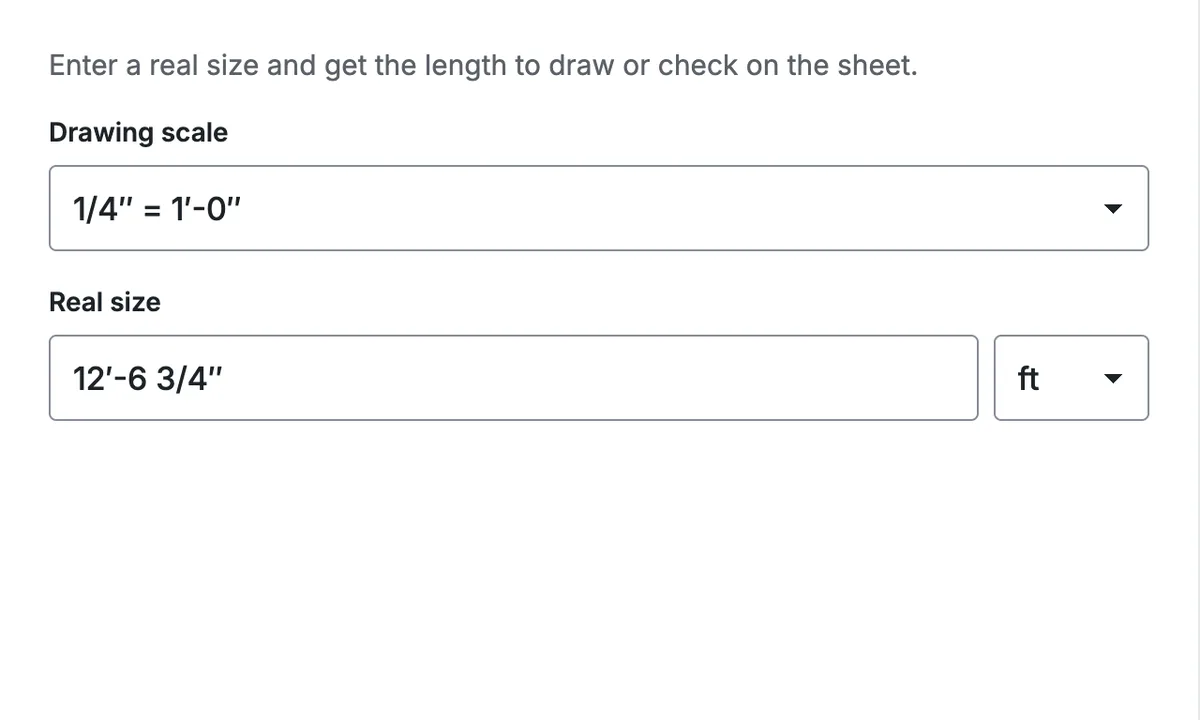
Convert a measurement on a drawing to real size, a real size to its length on paper, or one drawing scale to another, in architectural, engineering or metric scales.
An architectural scale calculator, also called a drawing scale converter, handles all three conversions with one number: the ratio of real size to drawn size that each scale sets. Beyond those conversions, the Architectural Scale Converter gives AutoCAD scale and text settings for each scale, recovers a missing scale from a single known length, and works out which scale a half-size print ends up at.
Three Scale Systems
Switch between imperial and metric scales, or type a custom ratio such as 1:30.
: Inches on paper per foot, such as 1/4″ = 1′-0″.: Feet per inch on paper, such as 1″ = 20′.: Ratios such as 1:50 or 1:100.
Works on Any Device
Sized for phone, tablet and desktop screens.
Desktop: Chrome, Edge, Firefox or Safari.iPhone: Safari on iPhone and iPad.Android: Chrome on Android phones and tablets.
Built for Design and Construction Teams
Architects: Check drawn lengths and rescale sheets.Contractors and estimators: Measure prints for quantity takeoffs.Interior designers: Size furniture at larger scales.Civil and landscape engineers: Read site plans in decimal feet.BIM and scan-to-BIM teams: Set sheet scales for model views.Architecture students: Print boards on smaller sheets.
Down to 1/32″: Feet-and-inch answers can keep fractions as fine as 1/32 of an inch.
Free, no account: Every mode works without sign-up or a usage limit.
Runs in your browser: Measurements stay on your device and are never uploaded.
Open source: Readable and reusable by anyone under the MIT license.
Quick scales: 1/4″ = 1′-0″ is a 1:48 ratio.: 1/8″ = 1′-0″ is a 1:96 ratio.: At 1:50, 1 cm on paper is 50 cm.: At 1:100, 1 cm on paper is 1 m.
Architectural Scale Calculator Accurate to 1/16 Inch
This architectural scale calculator rounds every fraction to the nearest 1/16″, or to 1/8″ or 1/32″ if you switch, so a 10′-8″ wall at 1/4″ = 1′-0″ reads 2 11/16″ on paper. The unrounded value stays on screen beside it, 2.6667″ or 67.7 mm here, so rounding never hides the exact number. Each rounding setting gives a different reading of that 2.6667″ line:
A 10′-8″ wall at 1/4″ = 1′-0″ under each rounding setting
1/8″
1/16″ (default)
1/32″
Exact
2 5/8″
2 11/16″
2 21/32″
2.6667″
Three things back the numbers:
Published table: Every architectural ratio matches the architectural scale table published by Archtoolbox.
65 automated tests: 25 of them check the math for conversions, length parsing and scale bars, and the rest check the page and shared links.
Open code: The formulas and their tests are public on GitHub, so any result can be checked against the code.
How to Convert Architectural Scale in 3 Steps
Converting an architectural scale with this converter takes three steps: choose a mode and drawing scale, type the measurement, then read the result in feet and inches, inches or millimeters.
1Choose a mode and scale.
Pick one of six modes: Drawing to real, Real to drawing, Rescale, Find the scale, AutoCAD or Print. Then pick a scale from the list, or type one that is not listed, such as 1:75 or 1″ = 25′.
2Type the measurement.
The field reads feet and inches in the forms people write them, such as 12′-6 3/4″, 12′ 6.75″ or 150.75″. Metric lengths work too, such as 3.81 m or 3,810 mm.
3Read, copy or share the result.
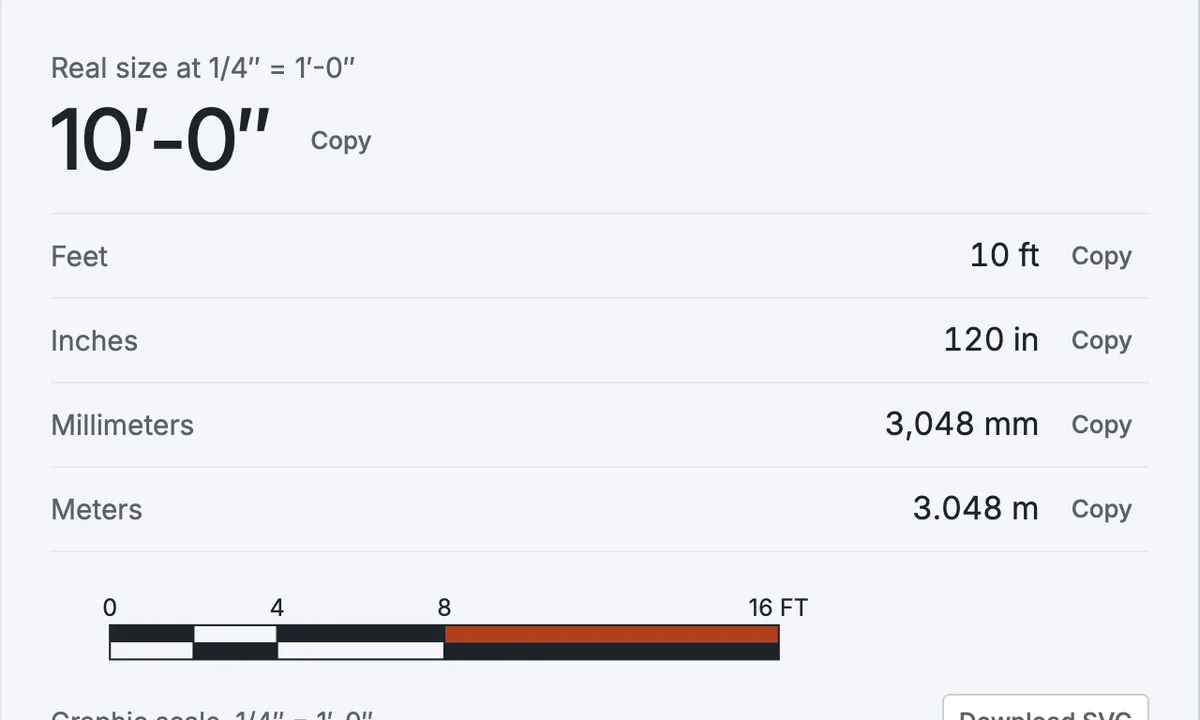
The main answer shows in large type with the other units under it. Each value has its own copy button, a share link keeps every input, and the scale bar downloads as an SVG.
In Drawing to real mode, 4 1/2″ measured at 1/8″ = 1′-0″ returns 36′-0″.
Convert Architectural Scale to Actual Size in Feet and Inches
To convert an architectural scale to actual size, multiply the length measured on the drawing by the scale ratio: 3 1/4″ measured at 1/4″ = 1′-0″ (ratio 48) is 3.25 × 48 = 156″, or 13′-0″. The converter shows the ratio with every result, so it never has to be worked out by hand. At 1/8″ = 1′-0″, the ratio of 96 turns a 3 3/8″ line into 27′-0″:
Actual size of a 3 3/8″ line at 1/8″ = 1′-0″
Measured on the drawing
× Ratio
= Actual size
3 3/8″
96 (1/8″ = 1′-0″)
27′-0″
The converter shows that result in five units at once:
27′-0″ in five units
Feet and inches
Decimal feet
Inches
Millimeters
Meters
27′-0″
27 ft
324 in
8,229.6 mm
8.2296 m
Metric drawings follow the same multiplication: 42 mm measured at 1:50 is 42 × 50 = 2,100 mm. If the print may have been resized, check its scale first with the converter's Find the scale mode.
Convert Inches or Millimeters to Architectural Scale
Inches convert to an architectural scale by dividing the real length by the scale ratio: a 15′-0″ wall (180″) at 1/4″ = 1′-0″ is 180 ÷ 48 = 3 3/4″ on paper. Millimeters take one extra step, since 3,810 mm is 150″ (3,810 ÷ 25.4) and 150 ÷ 48 gives 3 1/8″. The converter accepts 3,810 mm as typed.
Convert Drawing Scales from One Scale to Another
To convert drawing scales from one scale to another, divide the second number of the old ratio by the second number of the new one and print at that percentage: going from 1/8″ = 1′-0″ (1:96) to 1/4″ = 1′-0″ (1:48) is 96 ÷ 48 = 2, a 200% print. Six common changes show the pattern, with enlargements printing above 100% and reductions below it:
Print percentage for six common scale changes
From
To
Print at
Change
1/8″ = 1′-0″
1/4″ = 1′-0″
200%
Enlarge
1/4″ = 1′-0″
1/8″ = 1′-0″
50%
Reduce
1/4″ = 1′-0″
3/16″ = 1′-0″
75%
Reduce
1:100
1:50
200%
Enlarge
1/8″ = 1′-0″
1:100
96%
Reduce
1:20
1:50
40%
Reduce
A line and a square printed at 100% and at 200%.
The percentage applies to length, not area: a 200% print makes every line twice as long and covers four times the area. A full 24 × 36 sheet enlarged to 200% needs 48 × 72 in of paper, so only the part of the sheet in use is worth enlarging.
Most tools take the percentage as typed, with one exception:
Print dialog: In Adobe Acrobat's print dialog, choose Custom Scale and type the percentage.
Copier: On a copier, set the zoom or reduce/enlarge value to the same percentage.
CAD plot: In CAD, skip the percentage and plot at the new scale, such as 1/4″ = 1′-0″.
After any rescale, update the scale written on the sheet, since it still names the old scale.
Architecture Scale Converter with 32 Drawing Scales
An architecture scale converter with 32 drawing scales covers three systems: 12 architectural scales from 1/32″ to 3″ = 1′-0″, 8 engineering scales from 1″ = 10′ to 1″ = 200′, and 12 metric scales from 1:1 to 1:1000. Smaller fractions fit more building on a sheet, so one paper inch stands for 32′-0″ at 1/32″ = 1′-0″ but only 4″ at 3″ = 1′-0″:
Architectural scale conversion chart
Scale
Ratio
Inches per foot
1″ on paper equals
1/32″ = 1′-0″
1:384
0.03125
32′-0″
1/16″ = 1′-0″
1:192
0.0625
16′-0″
3/32″ = 1′-0″
1:128
0.09375
10′-8″
1/8″ = 1′-0″
1:96
0.125
8′-0″
3/16″ = 1′-0″
1:64
0.1875
5′-4″
1/4″ = 1′-0″
1:48
0.25
4′-0″
3/8″ = 1′-0″
1:32
0.375
2′-8″
1/2″ = 1′-0″
1:24
0.5
2′-0″
3/4″ = 1′-0″
1:16
0.75
1′-4″
1″ = 1′-0″
1:12
1
1′-0″
1-1/2″ = 1′-0″
1:8
1.5
8″
3″ = 1′-0″
1:4
3
4″
Engineering and metric scales convert to these architectural scales at fixed print percentages, and every scale has its own AutoCAD settings.
Architectural Scale to Engineering Scale Conversion
Architectural scale to engineering scale conversion lands close for only two engineering scales: 1″ = 10′ (1:120) sits next to 3/32″ = 1′-0″ (1:128), and 1″ = 30′ (1:360) next to 1/32″ = 1′-0″ (1:384), each 6.25% apart (a 93.75% print). The two series never match exactly because engineering ratios are multiples of 120, while architectural ratios come from fractions of an inch. Six of the eight engineering scales land nearest 1/32″ = 1′-0″, at print percentages from 93.75% to 625%:
Engineering scales, their closest architectural scale and the print percentage between them
Engineering scale
Ratio
Closest architectural
Print at
1″ = 10′
1:120
3/32″ = 1′-0″
93.75%
1″ = 20′
1:240
1/16″ = 1′-0″
125%
1″ = 30′
1:360
1/32″ = 1′-0″
93.75%
1″ = 40′
1:480
1/32″ = 1′-0″
125%
1″ = 50′
1:600
1/32″ = 1′-0″
156.25%
1″ = 60′
1:720
1/32″ = 1′-0″
187.5%
1″ = 100′
1:1,200
1/32″ = 1′-0″
312.5%
1″ = 200′
1:2,400
1/32″ = 1′-0″
625%
A civil site plan at 1″ = 20′ therefore joins a 1/16″ = 1′-0″ architectural set as a 125% print, not as a matching scale.
Architectural Scale to Metric Conversion
Architectural scale to metric conversion is close for four pairs, each about 4% apart: 1/2″ = 1′-0″ (1:24) and 1:25, 1/4″ (1:48) and 1:50, 1/8″ (1:96) and 1:100, and 1/16″ (1:192) and 1:200. Print percentages run from 25% for 1:1 to 260.42% for 1:1000, and the four close pairs all sit at 104.17%:
Metric scales, their closest architectural scale and the print percentage between them
Metric scale
Closest architectural
Print at
1:1
3″ = 1′-0″
25%
1:2
3″ = 1′-0″
50%
1:5
3″ = 1′-0″
125%
1:10
1″ = 1′-0″
83.33%
1:20
1/2″ = 1′-0″
83.33%
1:25
1/2″ = 1′-0″
104.17%
1:50
1/4″ = 1′-0″
104.17%
1:100
1/8″ = 1′-0″
104.17%
1:200
1/16″ = 1′-0″
104.17%
1:250
1/16″ = 1′-0″
130.21%
1:500
1/32″ = 1′-0″
130.21%
1:1000
1/32″ = 1′-0″
260.42%
A 4% gap still misreads real lengths: a 10 m wall drawn at 1:100 is 3.937″ long on paper, which a 1/8″ scale ruler reads as 31′-5 15/16″ instead of the true 32′-9 11/16″. Drawings from the UK and Australia are metric, so set the converter to 1:50 or 1:100 directly rather than to an imperial look-alike.
A 1/8″ scale ruler on a 10 m wall drawn at 1:100.
Architectural Scale Settings for AutoCAD
For any drawing scale, the AutoCAD mode returns four settings: scale factor, viewport scale, DIMSCALE and model-space text height. All four settings grow with the ratio, so halving the scale doubles each one, as the 1/8″ and 1/4″ rows show:
AutoCAD scale factor, viewport scale, DIMSCALE and model-space text height for five drawing scales
Scale (drawing units)
Scale factor
Viewport scale
DIMSCALE
Model-space text height*
1/8″ = 1′-0″ (inches)
96
1/96xp
96
9″
1/4″ = 1′-0″ (inches)
48
1/48xp
48
4 1/2″
1/2″ = 1′-0″ (inches)
24
1/24xp
24
2 1/4″
1″ = 20′ (feet)
20
1/20xp
20
1′-10 1/2″
1:100 (millimeters)
100
1/100xp
100
250 mm
* 3/32″ plotted, 2.5 mm on 1:100.
Drawings set up in feet divide the factor by 12, which is why 1″ = 20′ gives 20 rather than 240. The xp values use the paper-space scale format of the ZOOM command in Autodesk's AutoCAD help. The chart of AutoCAD scale factors lists the factor and XP value for every common scale.
Three of the four values are set in different parts of AutoCAD:
Viewport scale: Select the layout viewport and pick the scale from its scale list, or, with the viewport active, enter the xp value in the ZOOM command.
DIMSCALE: Enter it in Use overall scale of, on the Fit tab of the Dimension Style Manager, or type DIMSCALE at the command line.
Model-space text height: Enter it as the height of the text style or of the TEXT command.
With annotative text and dimension styles, AutoCAD sizes text and dimensions from each viewport's annotation scale, so DIMSCALE and model-space text height no longer need a separate value for each scale.
Find the Architectural Scale of a Drawing
To find the architectural scale of a drawing, measure one dimension whose real length you know and divide the real length by the measured length: a 20′-0″ wall that measures 5″ on the print gives 240″ ÷ 5″ = 48, a 1:48 ratio, which is 1/4″ = 1′-0″.
The longest written dimension or a grid spacing makes the best reference, since a longer length shrinks the effect of a small measuring error.
A print at true size lands on a standard ratio, while a resized print also needs the reprint percentage the converter shows:
True to scale: The ratio lands exactly on 1:48, the print is at 100%, and a 1/4″ scale ruler reads it directly.
Resized print: The same wall measured as 4 13/16″ gives a ratio of 1:49.87, so the closest architectural scale is 1/4″ = 1′-0″, the print is at 96.25% of true size, and a 103.9% reprint restores it.
1:48 · 1/4″ = 1′-0″ · printed at 100%
A 20′-0″ wall that measures 5″ on the print.
The Compare with menu starts on architectural scales, which suits drawings dimensioned in feet and inches; a drawing dimensioned in millimeters needs the metric or all-scales setting instead.
Drawing Scale Converter for A1 to A3 and Half-Size Prints
A drawing scale converter for A1 to A3 and half-size prints shows the new scale when a sheet prints on a smaller one: A1 on A3 prints at about 50%, so a 1:50 plan becomes 1:100, and a 24 × 36 ARCH D sheet on 12 × 18 ARCH B turns 1/4″ = 1′-0″ into 1/8″ = 1′-0″. Fit to page, a setting in print dialogs and PDF viewers, shrinks a sheet by the tighter of its two sides:
Fit-to-page percentage and closest standard scale for four sheet changes
From
To
Print at
Closest standard scale
A3 (297 × 420 mm)
49.94%
1:100 (exact)
A3
35.32%
1:200 (not exact, true ratio 1:141.6)
ARCH B (12 × 18 in)
50%
1/8″ = 1′-0″ (exact)
ANSI B (11 × 17 in)
45.83%
1/8″ = 1′-0″ (not exact, true ratio 1:104.7)
The sheet sizes come from ASME Y14.1 for ANSI, ISO 216 for A sizes and the ARCH series common on US architectural sets.
49.94% · 1:50 → 1:100 (exact)
A1 fitted to A3 prints at 49.94%, so 1:50 becomes 1:100.
Adobe Acrobat's Fit option sizes a sheet to the printer's printable area, which stops short of the paper edge, so a real fit-to-page print can come out slightly smaller than the table shows. To land exactly on 1:100 or 1/8″ = 1′-0″ in the two exact rows, print at 50% instead of fitting the page, accepting that the printer may trim a thin strip at the sheet edge.
When the new scale is not standard, the converter gives the true ratio to measure with, and the graphic scale bar still reads correctly because it shrinks with the drawing.
Free Online Scale Converter for Architecture, No Sign-Up
The Architectural Scale Converter is a free online scale converter for architecture that runs in any modern desktop or phone browser, with no sign-up, no ads and nothing to install. Two free extras sit beside the six modes:
No ads or tracking: The page loads no ad, analytics or tracking scripts, so nothing competes with the converter on screen.
Print-ready scale bars: A downloaded scale bar is a black SVG sized in millimeters, so it prints at true size.
Blueprint Scale Converter for Every Trade
A blueprint scale converter serves six groups who read drawings at different scales: architects, contractors and estimators, interior designers, civil and landscape engineers, BIM and scan-to-BIM teams, and architecture students. Each trade leans on a different one of the six modes, from rescaling sheets to setting CAD viewports.
Scale Conversions for Architects
Architects enlarge parts of a plan into details and need the exact copy percentage: taking a wall section from 1/4″ = 1′-0″ to 1 1/2″ = 1′-0″ is a 600% enlargement. Any other percentage leaves the detail sheet off its stated scale.
Rescale mode
Copy 1/4″ = 1′-0″ to 1-1/2″ = 1′-0″ at
600%
Size factor
× 6
Direction
Enlarge
The converter's result for the example above.
Scale Conversions for Contractors and Estimators
Contractors and estimators confirm a print is to scale before a takeoff: a 30′-0″ dimension that measures 3 11/16″ points to 1/8″ = 1′-0″ printed at 98.3%, so a 101.7% correction brings every length back. Left uncorrected, a 100 ft run would measure as about 98 ft. The same check applies to building construction detail drawings, which are drawn at larger scales. Contractors who need as-built drawings from a scan can compare the best scan to BIM services in US before ordering one.
Find the scale mode
Closest standard scale
1/8″ = 1′-0″
Measured ratio
1:97.63
Print size vs. true scale
98.33%
Reprint at
101.69%
The converter's result for the example above.
Scale Conversions for Interior Designers
Interior designers draw furniture from catalog sizes: a 7′-6″ sofa is 3 3/4″ long at 1/2″ = 1′-0″, twice its 1 7/8″ length at 1/4″ = 1′-0″. Converting the real size gives the length to draw without dividing by hand.
Real to drawing mode
Length on the drawing at 1/2″ = 1′-0″
3 3/4″
Inches
3.75 in
Millimeters
95.3 mm
The converter's result for the example above.
Scale Conversions for Civil and Landscape Engineers
Civil and landscape engineers work in decimal feet for grades and site layout: 2 7/8″ at 1″ = 30′ reads 86.25 ft, which the converter also shows as 86′-3″.
Drawing to real mode
Real size at 1″ = 30′
86′-3″
Feet
86.25 ft
Meters
26.289 m
The converter's result for the example above.
Scale Conversions for BIM and Scan-to-BIM Teams
BIM and scan-to-BIM teams model at full size, so a scale only enters through the view: each view carries a scale that sizes annotation and sets its default detail level, while the model elements follow their BIM level of development. When those views go onto AutoCAD sheets, the AutoCAD mode gives the matching viewport and DIMSCALE values, such as 1/32xp and 32 at 3/8″ = 1′-0″. Before modeling from scan data, a point cloud density calculator shows whether the point spacing suits the job.
AutoCAD mode
AutoCAD scale factor for 3/8″ = 1′-0″
32
Viewport scale (ZOOM)
1/32xp
DIMSCALE
32
The converter's result for the example above.
Scale Conversions for Architecture Students
Architecture students print boards on whatever paper the plotter takes: an 18 × 24 sheet at 1/4″ = 1′-0″ printed on 12 × 18 paper lands at 66.7%, a 1:72 ratio that matches no standard scale.
Print mode
Print ARCH C on ARCH B at
66.67%
Scale on the new sheet
1:72
Closest standard scale
3/16″ = 1′-0″ (not exact)
The converter's result for the example above.
Frequently Asked Questions About Architectural Scales
What Is an Architectural Scale?
An architectural scale is a drawing ratio written as inches on paper for each foot of building, such as 1/8″ = 1′-0″, which equals 1:96. An architectural scale also names the architect's scale ruler printed with these ratios, usually a three-sided ruler that carries several scales on its faces.
How Do You Calculate Architectural Scale?
You calculate an architectural scale by dividing 12 by the inches on paper that stand for one foot: 3/16″ = 1′-0″ is 12 ÷ 0.1875 = 64, a ratio of 1:64.
Is 1.75 an Actual Architectural Scale?
No, 1.75 is not a standard architectural scale: as 1 3/4″ = 1′-0″ it is about 1:6.86, between the standard 1 1/2″ (1:8) and 3″ (1:4) scales. Typed as 1:75, it works as a custom ratio.
What Is a Scale Factor?
A scale factor is the number you multiply a drawing measurement by to get real size: for 1/2″ = 1′-0″ it is 24. In inch-based CAD drawings the same number sets text and dimension sizes. The chart of architectural scale factors gives the factor for each scale from 1/32″ to 3″ = 1′-0″.
What Is the Difference Between Architectural and Engineering Scales?
The difference between architectural and engineering scales is the unit: architectural scales give inches of paper per foot and read in feet and inches, while engineering scales give feet per inch of paper and read in decimal feet.
How Do You Read an Architectural Scale?
To read an architectural scale, use the face marked with the drawing's scale, count whole feet from zero in one direction, and read inches on the divided section past zero. On the 1/4″ face, 3 foot marks plus 6 inch marks read 3′-6″. The U.S. Fire Administration guide Using Engineer and Architect Scales shows the same method.
What Scale Are Architectural Drawings?
Architectural drawings use the scale that fits the sheet and shows the needed detail: floor plans at 1/4″ or 1/8″ = 1′-0″, details at 1 1/2″ or 3″ = 1′-0″, site plans at engineering scales, and physical models at 1:500 to 1:20, depending on what they show. Metric sets use 1:50 or 1:100 for plans and 1:5 to 1:20 for details. The plan and detail ranges match the drawing scale slides of New York City College of Technology (CUNY). The guide to types of architectural drawings explains what each of those sheets shows.
What Is the Most Common Architectural Scale?
The most common architectural scale in US drawing sets is 1/4″ = 1′-0″ (1:48), because a 60′-0″ house is only 15″ long at that scale and still fits a 24 × 36 sheet with room for dimensions and notes.
What Are Common Architectural Scales for Site Plans?
Site plans usually use engineering scales such as 1″ = 20′, 1″ = 30′ or 1″ = 40′, or an architectural 1/32″ or 1/16″ = 1′-0″.
What Scale Are Architectural Models?
Architectural models take their scale from what they must show: site models at 1:500 or 1:1000, building models at 1:200 or 1:100, and interior or detail models at 1:50 or 1:20. Among architectural scales, 1/16″, 1/8″ and 1/4″ = 1′-0″ (1:192, 1:96 and 1:48) sit closest to 1:200, 1:100 and 1:50.
What Is 1/4 Scale in Architecture?
In architecture, 1/4 scale means 1/4″ = 1′-0″, so a quarter inch on the drawing equals one foot of building, a ratio of 1:48, and a 3″ line on the plan is 12′-0″.
Is 1/4 Scale the Same as 1/4 Inch Scale?
No, 1/4 scale and 1/4 inch scale are different: a 1/4 scale model or figure is 1:4, a quarter of real size, while 1/4 inch scale is 1:48, so the model is twelve times larger than a 1/4″ drawing.
What Is 1/8 Scale in Feet?
1/8 scale in architecture means 1/8″ = 1′-0″, a 1:96 ratio, so a 2 1/2″ line on the drawing is 20′-0″ in feet.
What Is 1:100 in Feet and Inches?
At 1:100, one inch on the drawing equals 100 inches, or 8′-4″, so a 3″ line is 25′-0″.
How Do You Convert 1:20 Scale to Full Size?
To convert 1:20 scale to full size, multiply the drawing measurement by 20, so 35 mm on a 1:20 drawing is 700 mm full size.
Is There an Online Scale Converter Available?
Yes, an online scale converter is available: the Architectural Scale Converter converts between drawing size and real size in both directions, with no download.
Is the Architectural Scale Converter Free?
Yes, the Architectural Scale Converter is free, and no feature sits behind a paid plan.
Is There an Architectural Scale Calculator App?
No, the Architectural Scale Converter has no separate app; it runs in phone browsers and can be added to a home screen like any website, so it opens in one tap.
Are My Drawings Uploaded Anywhere?
No, your drawings are never uploaded: the converter only uses the numbers you type, and every calculation runs in your browser, so nothing is sent to a server.
What Is the Best Free Architectural Scale Converter?
The best free architectural scale converter reads feet-and-inch fractions, covers architectural, engineering and metric scales, and can find an unknown scale. The Architectural Scale Converter does all three.
FREE · NO SIGN-UP · RUNS IN YOUR BROWSER
Ready to convert a scale?
Have a measurement off a printed drawing?
Is the scale missing, or does the print look resized?