Construction drawings
Typical Detail Drawing: Meaning, Components, Scales, and Construction Uses
A typical detail drawing is an enlarged construction drawing that explains a recurring building condition, such as a window sill, roof edge, wall junction, or pipe sleeve. Rather than redrawing a similar assembly at every location, the design team documents a representative solution and identifies where it applies. The drawing shows materials, dimensions, relationships, and notes needed to understand the intended construction. It does not automatically apply to every condition that merely looks similar.
This guide explains how typical details work, what the notation TYP or TYPICAL means, and how an enlarged construction detail differs from a building section. It also covers common architectural, structural, and MEP examples; essential drawing information; specifications and shop drawing responsibilities; and the checks needed before a standard library detail is issued for construction.
What Is a Typical Detail Drawing?
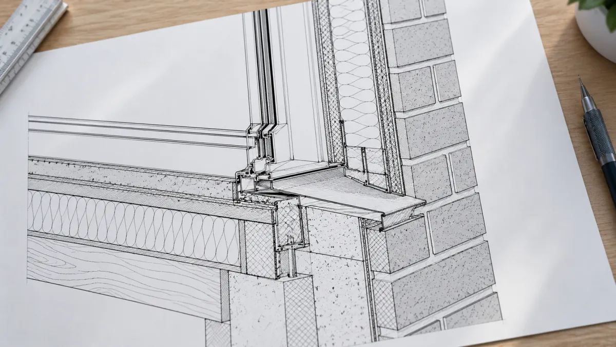
A typical detail drawing illustrates a repeated construction assembly at a scale that makes its parts and connections understandable. It may describe flashing at a window, the meeting of a wall and slab, or a mechanical penetration. Its purpose is consistency: one correctly referenced and coordinated detail can explain several comparable project locations.
Consider an exterior window sill. A floor plan locates the opening, and an elevation shows its appearance. A typical window detail can indicate the sill slope, flashing continuity, air or water barrier relationship, and position of adjacent materials. The detail communicates the design requirement; product specifications and applicable installation instructions may provide additional information.
Calling a condition typical does not eliminate differences between openings. A sill above a masonry veneer may need different drainage and support provisions from one in a curtain wall. The drawing author must decide whether one detail genuinely covers both situations or whether separate construction detail drawings are necessary.
What Does TYPICAL Mean on a Set of Construction Drawings?
TYPICAL or TYP generally identifies information intended to apply to comparable instances defined by the drawings and notes. It helps avoid duplicating the same assembly description throughout a set. However, its scope depends on project conventions, callouts, and specifications, so the label alone should never override clearly different site conditions or detail references.
For example, a recurring interior partition head may refer to one standard junction. If one partition meets a rated slab edge while the others meet an ordinary ceiling, that location may need an exception or dedicated detail. A note such as “typical except where noted” still requires the documents to identify what is different.
Read the reference bubble, keynote, wall type, and adjacent general notes together. Some projects apply a typical detail through a general note; others reference each applicable location on a plan or section. Neither convention excuses a designer from checking that the represented assembly is appropriate for its actual location.
The main risk is false repetition. Using one generic detail across different substrates, fire ratings, movements, or exposures can introduce contradictory requirements. An enlarged typical wall detail should be rechecked whenever those conditions change, even if the outline looks nearly identical.
How Is a Typical Detail Different From a Section or Wall Section?
A building section cuts through a larger portion of the structure to explain levels and spatial relationships. A wall section concentrates on the buildup of one wall from floor or foundation to roof. A typical construction detail enlarges a smaller interface, allowing the designer to explain connections that the broader views cannot show clearly. As for what type of drawings show how each wall is constructed, wall sections are the primary source.
| Drawing view | Main purpose | Example |
|---|---|---|
| Building section | Explain the relationship among floors, walls, and roof levels | A section through two stories |
| Wall section | Identify layers and vertical junctions in a wall assembly | Exterior wall from footing to eave |
| Typical detail | Describe a repeated, specific construction condition | Window sill flashing or partition head |
| Special detail | Resolve a location that differs from the usual assembly | Unusual expansion joint or corner |
A single wall section may call out several enlarged construction details: one at the foundation, another at the window head, and a third at the parapet. That organization avoids overloading the larger view with small notes while preserving the context needed to locate each junction.
The drawing scale reflects what must be communicated. US sets often use larger imperial scales for details than for general floor plans; metric drawings may use 1:10, 1:5, or other appropriate scales. There is no single scale that guarantees a detail is buildable. Choose one that makes required dimensions and layers readable.
Which Types of Typical Construction Details Are Common?
Typical construction details cover recurring conditions across architectural, structural, mechanical, electrical, plumbing, and civil work. Their names follow the assemblies involved rather than one universal list. The useful distinction is whether a detail addresses a wall or roof interface, an engineered connection, a service penetration, or an external site component.
| Detail family | Common examples | Coordination issue |
|---|---|---|
| Architectural envelope | Window sill, door jamb, roof edge, parapet | Moisture control and assembly continuity |
| Interior architecture | Partition head, ceiling perimeter, stair trim | Finishes, movement, and rated assemblies |
| Structural | Footing joint, slab edge, steel connection | Loads, anchorage, reinforcement |
| Mechanical | Duct branch, fire damper, equipment support | Clearance, support, service access |
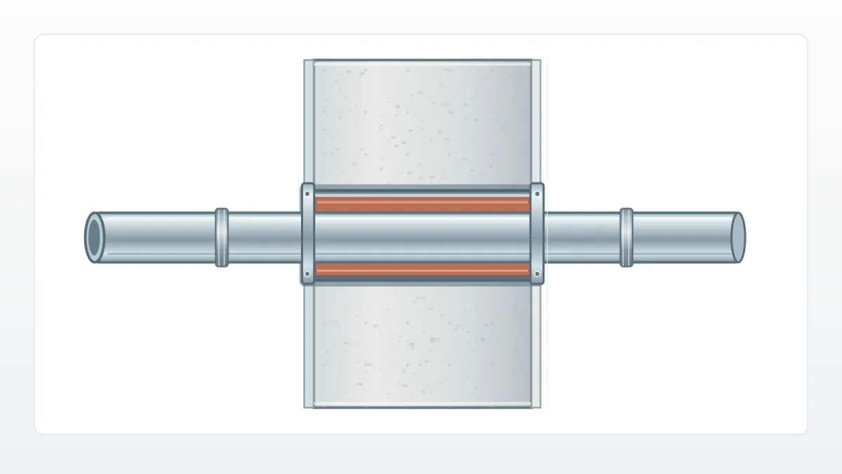
| Plumbing | Pipe sleeve, cleanout, roof penetration | Sealing, drainage, maintainability |
| Electrical | Equipment mounting, conduit penetration | Access, grounding, and interfaces |
| Site and utilities | Paving edge, trench, manhole connection | Grades, drainage, underground services |
These are families of drawings, not a statement that one office must create a separate typical detail for every row. A fire damper condition, for instance, may require mechanical information coordinated with the wall's fire-resistance requirements and approved product installation instructions.
Common architectural details are particularly sensitive to changes in exposure and substrate. A flashing detail for a sheltered opening may not suit a wind-driven-rain exposure. Likewise, a typical structural connection is only suitable where the design assumptions and loads remain applicable. The project documents must identify the limits of reuse.
What Information Should a Typical Detail Drawing Contain?
A useful typical detail drawing combines a legible enlarged view with references that explain where it belongs and what it requires. It ordinarily identifies the assembly, dimensions or clearances, materials, annotations, and related specifications. A detail number and sheet reference help readers follow the connection from a plan or section to its technical explanation.
| Drawing component | Why it matters |
|---|---|
| Detail title and number | Identifies the intended assembly and the referenced view |
| Suitable scale | Makes layers and interfaces readable |
| Dimensions and levels | Defines relevant distances, laps, offsets, or elevations |
| Material hatches and notes | Distinguishes assembly layers and products by reference |
| Keynotes and leader lines | Directs readers to particular features or instructions |
| Adjacent construction | Shows what the assembly connects to |
| Exceptions and conditions | Prevents misapplication at unlike locations |
| Revision and issue status | Shows which detail is current |
A label such as 4/A-501 is an illustrative detail reference: the number identifies a view and the sheet code identifies its location. Actual sheet numbering varies by office. The associated callout should agree with the detail title and the relevant plan, section, or schedule.
For a window sill, show the arrangement and continuity of the weather-resistive system, the frame relationship, and the dimensions that are important to the design. Do not invent a universal flashing lap or fastener spacing. Those requirements depend on the specified assembly, manufacturer instructions, testing, and applicable construction documents.
A detail is not complete merely because it contains many annotations. Check whether the reader can identify the substrate, adjacent layers, drainage path, and any special condition. Avoid repeating the same material requirement in multiple places if separate descriptions could conflict when the design changes.
How Do Detail Drawings, Specifications, and Shop Drawings Work Together?
A construction detail communicates geometric design intent and how parts are meant to meet. The specification states material, performance, quality, and execution requirements. Shop drawings, when required, present a contractor's or fabricator's proposed way of making and installing selected work. All three must be coordinated, but they do not have interchangeable contractual roles.
For a metal coping at a parapet, the architectural detail might show profile, slope, edge relationships, and a movement joint. The specification may define permitted materials, finishes, performance, and submittals. A sheet-metal fabricator's shop drawing develops the proposed pieces and installation arrangement for review. None should silently contradict the others.
Under common AIA A201-2017 conditions, shop drawings are submittals rather than contract documents, and the contractor checks their coordination before sending them for the stipulated design review. The actual approval process depends on the project's governing agreement. A review mark is not a blanket authorization to depart from the contract requirements.
Should a Typical Detail Drawing Name a Product?
A typical detail may identify a product when the project documentation calls for it, but the name must agree with the specifications and approved selections. Many teams prefer a material designation or keynote, leaving brand-specific requirements in a schedule or specification. Consistency is more important than a universal rule about where every product name belongs.
For example, a waterproofing note can refer to an approved membrane system instead of embedding a potentially outdated product name into several typical architectural details. Where proprietary components affect geometry, the detail must still reflect their real installation requirements. If the specification and detail disagree, seek clarification rather than choosing whichever instruction is easier.
How Is a Typical Detail Developed and Checked Before Construction?
The workflow begins by identifying recurring conditions in the plans and sections, then producing a detail suitable for those locations. Designers coordinate dimensions, materials, and related specifications before issuing it. During construction, required shop drawings and requests for information may reveal conditions that need clarification, revision, or a separate non-typical detail.
- Identify repeated assemblies. Review plans, wall types, sections, and locations where the same construction is proposed. Note variations in exposure, substrate, fire rating, or movement.
- Draw the junction clearly. Choose a suitable scale and show the relevant layers, dimensions, notes, and connection to adjacent work.
- Reference it correctly. Place callouts or general notes according to the project's documentation conventions, and confirm that sheet numbers match the issued detail.
- Coordinate the disciplines. Check the architectural assembly against structural supports, MEP penetrations, and required clearances where applicable.
- Compare with specifications. Confirm that material names, performance notes, and installation requirements do not contradict the written requirements.
- Review submitted information. When shop drawings are required, check the submittal against the construction documents within the reviewer's contractual scope.
- Audit exceptions and revisions. Find locations where the usual assembly does not apply, issue distinct information when needed, and carry approved changes into the controlled set.
A parapet illustrates why the final step matters. Several roof edges may use one coping detail, but a higher parapet or a different roof membrane termination can change the assembly. A callout audit checks for that exception before fabrication or installation proceeds. The goal is not eliminating every future question; it is avoiding preventable ambiguity.
Can You Reuse Details From a Standard Drawing Library?
Standard detail libraries are useful starting points for recurring components, particularly in institutional facilities and infrastructure projects. They can improve consistency and reduce repeated drafting. But a borrowed typical detail must still be checked against the actual project's materials, geometry, climate exposure, codes, and owner requirements before it becomes an issued construction instruction.
For example, the University of Texas at Austin publishes standard detail drawings for its facilities while expressly treating them as guidelines that need modification for individual projects. Its approach illustrates the distinction between a reusable reference and a fully coordinated project deliverable. A detail's availability in a CAD library does not mean it has been approved for a different building.
The U.S. National Park Service likewise distinguishes typical construction details from special conditions in its documentation requirements and calls for section and detail references to agree across the drawing set. A borrowed window head, foundation joint, or pipe sleeve still needs technical review by the responsible team.
The best practice is to reuse the design logic, not assume universal applicability. Verify the proposed condition, update references and notes, coordinate with specifications, and clearly identify exceptions. A typical detail drawing is valuable precisely because it makes repeated construction information understandable without concealing the differences that matter.